Download
1 / 17
170 likes | 357 Vues
EE534 VLSI Design System Summer 2003 Lecture 9:Chapter 7 Combinational MOS logic circuits. I sc 0. I sc I max. Impact of C L on P sc : slop engineering. Vin. Vout. Vin. Vout. C L. C L. Large capacitive load Output fall time significantly larger than input rise time.

E N D
EE534VLSI Design SystemSummer 2003 Lecture 9:Chapter 7Combinational MOS logic circuits
Isc 0 Isc Imax Impact of CL on Psc:slop engineering Vin Vout Vin Vout CL CL Large capacitive load Output fall time significantly larger than input rise time. Small capacitive load Output fall time substantially smaller than the input rise time.
Review: CMOS inverter static power • Static power consumption: • Static current: in CMOS there is no static current as long as Vin < VTN or Vin > VDD+VTP • Leakage current: determined by “off” transistor • Influenced by transistor width, supply voltage, transistor threshold voltages VDD VDD Ileak,p VDD VI<VTN Vo(low) Vcc Ileak,n
Review: Dynamic Power Consumption Vdd Vin Vout CL
Review: Short Circuit Power Consumption Vin Isc Vout CL Finite slope of the input signal causes a direct current path between VDD and GND for a short period of time during switching when both the NMOS and PMOS transistors are conducting.
Review: CMOS inverter power dissipation P = CL VDD2 f + tscVDD Ipeak+VDD Ileakage Short-circuit power (~8% today and decreasing absolutely) Leakage power (~2% today and increasing) Dynamic power (~90% today and decreasing relatively)
Combinational vs. Sequential Logic Output = ( ) f In, Previous In Output = ( ) f In
Static vs. Dynamic CMOS • In static circuits at every point in time (except when switching) the output is connected to either GND or VDD via a low resistance path. • fan-in of N requires 2N devices • Dynamic circuits rely on the temporary storage of signal values on the capacitance of high impedance nodes. • requires only N + 2 transistors • takes a sequence of precharge and conditional evaluation phases to realize logic functions
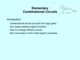
CMOS Logic Circuits 7 Large scale integrated CMOS logic circuits such as watched, calculators, and microprocessors are constructed by using basic CMOS NOR and NAND gates. Therefore, understanding of these basic gates is very important for the designing of very large scale integrated (VLSI) logic circuits.
Static complimentary CMOS • Complementary pullup network (PUN) and pulldown network (PDN) • Only one network is on at a time • PUN: PMOS devices • PDN: NMOS devices • PUN and PDN are dual networks • Output is always connected to Vcc or Gnd A PUN B C F A PDN B C Why NMOS should be used as a pull-down and pMOS should be used a pull-up device?
CL CL CL CL Threshold Drops VDD VDD PUN S D VDD D S 0 VDD 0 VDD - VTn VGS PDN VDD 0 VDD |VTp| VGS D S VDD S D
Construction of PDN • NMOS devices in series implement a NAND function • NMOS devices in parallel implement a NOR function A • B A B A + B A B
CMOS NAND A B A • B A B A B
CMOS NOR B A A + B A B A B
B A C D Complex CMOS Gate OUT = !(D + A • (B + C)) A D B C
CMOS gate design • Designing a CMOS gate: • Find pulldown NMOS network from logic function or by inspection • Find pullup PMOS network • By inspection • Using logic function • Using dual network approach • Size transistors using equivalent inverter • Find worst-case pullup and pulldown paths • Size to meet rise/fall or threshold requirements
weaker PUN • The threshold voltage of M2 is higher than M1 due to the body effect () VTn1 = VTn0 VTn2 = VTn0 + ((|2F| + Vint) - |2F|) since VSB of M2 is not zero (when VB = 0) due to the presence of Cint VTC is Data-Dependent 0.5/0.25 NMOS 0.75 /0.25 PMOS A B M3 M4 F= A • B D A M2 S VGS2 = VA –VDS1 D Cint B M1 S VGS1 = VB