Download
1 / 69
690 likes | 856 Vues
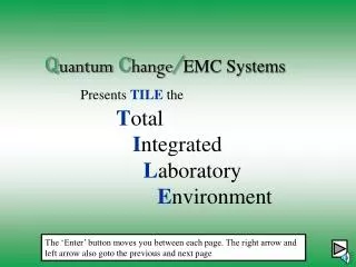
Q uantum C hange / EMC Systems Presents TILE the T otal I ntegrated L aboratory E nvironment. The ‘Enter’ button moves you between each page. The right arrow and left arrow also goto the previous and next page. Quantum Change/EMC Systems. Overview Designed to support all types of testing

E N D
QuantumChange/EMC SystemsPresents TILE the TotalIntegratedLaboratoryEnvironment The ‘Enter’ button moves you between each page. The right arrow and left arrow also goto the previous and next page
Quantum Change/EMC Systems • Overview • Designed to support all types of testing (radiated immunity and emissions, conducted immunity and emissions)
Quantum Change/EMC Systems • Overview • Designed to support all types of testing (radiated immunity and emissions, conducted immunity and emissions) • Designed for all Test Standards IEC, FCC, Mil-Std, SAE, Automotive, Medical and other specialized specifications
Quantum Change/EMC Systems • Overview • Designed to support all types of testing (radiated immunity and emissions, conducted immunity and emissions) • Designed for all Test Standards IEC, FCC, Mil-Std, SAE, Automotive, Medical and other specialized specifications • Designed to support all manufacturers of EMC hardware
Quantum Change/EMC Systems • Overview (Continued) • 32 Bit application is native under Win95, Win 98, Win NT (above 3.51) and Win2000
Quantum Change/EMC Systems • Overview (Continued) • 32 Bit application is native under Win95, Win 98, Win NT (above 3.51) and Win2000 • Site Licensed for flexibility Load it on as many PC’s in your lab as required. A separate hardware lock is not required for each machine.
Quantum Change/EMC Systems A TILE profile is a completely defined test.
Quantum Change/EMC Systems A TILE profile is a completely defined test. Each Profile has a minimum 5 windows. The front window is called the Flowchart.
Quantum Change/EMC Systems Each icon on the screen performs a step in the test. The user/designer of the test has control of almost every parameter that is reasonable.
Quantum Change/EMC Systems The Palette of tools varies depending upon the options purchased. This palette shows most all icons currently found in the TILE software.
Quantum Change/EMC Systems Double-clicking on any icon gives you access to ‘Edit/Execute or Run’ choices. You can ‘Execute’ any step on a flowchart. ‘Go’ causes the complete chain of icons to execute.
Quantum Change/EMC Systems Editing gives the user access to all settings of this step. Each step is unique, so different settings can apply for the same type of action in different steps of a profile.
Quantum Change/EMC Systems The tabs identify different types of settings that can be modified. The Action tab identifies the version information for this icon. This information is used when doing troubleshooting or checking upgrades.
Quantum Change/EMC Systems From the flowchart, there are system icons to move between each of the 5 standard windows. These windows are the ‘Flowchart’, ‘Data’ , ‘Instrument’, ‘Log’ and ‘Audit Trail’
Quantum Change/EMC Systems Data window shortcut icon The Data window displays all the various pieces of information tracked within the profile. The first column is the data element name. This can be any name that is unique for the designer/user. Names which reflect their purpose make understanding the information much easier.
Quantum Change/EMC Systems The ‘DB’ refers to linkages with the TILE/DB database product. The ‘Valid’ refers to the current number of valid data points in this element. The ‘Type’, ‘Intp’ and ‘Source’ columns all deal with the data type and its source.
Quantum Change/EMC Systems New Data icon Double clicking on any line, or hitting ‘New Data’ gives you access to the data definition. There are 8 types of data: ‘Measurement’s are results of reading an instrument, ‘File’ refers to data from a text file (correction factors, specification limits, etc), ‘Equation’s are math processes, ‘Preset’s are data created internally for reference purposes, ‘Word’ data is alpha-numeric data (such as comments) that is linked by frequency. Finally, ‘Direct’ data is frequency and amplitude data entered directly through TILE’s direct entry process.
Quantum Change/EMC Systems The ‘Continuous (Linear)’ and ‘Continuous (Log)’ buttons give the user/designer control of how the TILE program will interpolate data. Turning both off will cause there to be no interpolation. This is important for displaying data in graphs or windows. You do not want to interpolate failure information, for instance. You only want to report the actual frequencies of failure.
Quantum Change/EMC Systems The ‘Save to Database’ controls whether this information is automatically stored in the related TILE/DB database product. The ‘Auto Sort’ determines whether the data element is sorted by frequency when it is first created.
Quantum Change/EMC Systems The ‘Values’ tab gives the user access to the values currently stored in this data element. You can also change the sorting direction on this page. The values shown can only be viewed, not modified. This insures data security.
Quantum Change/EMC Systems Instrument window shortcut icon The Instrument window gives the user access to which instruments will be used within a profile and what they will be referred to by name. Above you can see a signal generator, called ‘SigGen’, defined.
Quantum Change/EMC Systems The line shows the instrument name, for use within the profile, the ‘type’, the interface (GPIB, Serial, etc), the current instrument driver (which actual instrument is present), the version number for this instrument driver (defined by Quantum Change), the Serial Number and Calibration Date.
Quantum Change/EMC Systems New instrument Icon Double-clicking on any instrument gives the user access to the definitions for this instrument. Changing the ‘Driver’ (which instrument is actually being used) and the ‘Address’ (Buss/Serial etc.) are the most common changes. Currently, Tile supports over 300 different instruments. New instruments drivers are added constantly. Our commitment is to support every instrument you own, that is appropriate for an EMC test.
Quantum Change/EMC Systems Log window shortcut icon The Log Windows allows the user to display a history of GPIB/Serial commands sent to the various defined instruments. This is used, primarily, for debugging problems. The default behaviour is to have the log turned OFF.
Quantum Change/EMC Systems Audit trail shortcut icon The Audit Trail provides a document history of the settings for each icon on the flowchart. It is used for documentation purposes. The action name, in this case ‘Immunity - 10 Vrms’ is matched to the icon on the flowchart. The remainder of this printout displays the internal settings for this step.
Quantum Change/EMC Systems Beyond the standard 5 windows you can have as many separately defined graphs and tables as you need. It is as simple as clicking on ‘Window/Add/..’. If you select ‘Graph’ a new, blank graph is created. If you select ‘Table’ a new blank table is created.
Legends Quantum Change/EMC Systems Titles (3 Lines) Graphs are defined in a static view, with data updating constantly. You define what data to include and other display options and the graph will be constantly updated to reflect changing data. User Controlled information Data
Quantum Change/EMC Systems Graphs can be exported to disk as windows metafiles (.wmf), a special version of a standard bitmap that is supported by most word processors or copied to the clipboard to be pasted . You can configure as many different graphs as you need. Each with different data, frequency ranges, titles, etc.
Quantum Change/EMC Systems The same basic options apply for table definition. The titles for columns, column widths and decimal accuracy can be specified.
Quantum Change/EMC Systems Tables can be automatically saved to disk as comma-separated text files (.csv). They can be copied to the clipboard and pasted into other applications (such as word processors or spreadsheets). Remember, you can have as many different tables as you need. Each designed to display different views of the available data.
Quantum Change/EMC Systems It would never do to discuss the TILE software and not demonstrate the power of each action found within the program. Actions are broken up into six general categories - emission actions, immunity actions, information actions, utility actions, GTEM actions and miscellaneous actions. We will next run through a quick summary of each type of action.
Quantum Change/EMC Systems Emissions Actions
Quantum Change/EMC Systems Immunity Actions
Quantum Change/EMC Systems Information Actions
Quantum Change/EMC Systems Utility Actions
Quantum Change/EMC Systems GTEM Actions
Quantum Change/EMC Systems Miscellaneous Actions
Quantum Change/EMC Systems To demonstrate the power of the TILE software, we are going to step through the options found in two actions - Immunity Test and Optimize (an Emissions Scan).
Quantum Change/EMC Systems When editing an action, the first page is called ‘Action’. It provides a place for the user to name this step of the test. The name of the test is important since it will show up on any drop-down box that allows you to specify actions. This page also displays the Version number, DLL name and a short description of what type of test or activity this action performs. Also visible are all the tabs relevant for this action. Immunity is the most complex action in the TILE system as can be seen by the number of tabs.
Quantum Change/EMC Systems The frequency tab allows the designer to select 4 different methods of determining frequency. You can specify percent steps, with fractions acceptable, log steps, linear steps or you can use the ‘Set from Data’ switch and point to a data element with a specific set of frequencies.
Quantum Change/EMC Systems The ‘Freq Step’ tab gives the user control of some unique capabilities within TILE. When performing a immunity test, the software will normally step to a frequency, turn on the signal generator, set the expected output level, check the level, turn on modulation, delay the required time and then turn off modulation, set the rf to a minimum level and turn off the signal generator. Many of these steps are not desired for certain types of equipment. With this tab, the designer can customize the level loop to fit their requirements.
Quantum Change/EMC Systems In the ‘Primary Amp’ tab a data element is selected which represents the level to which the primary leveling loop will aim. The ‘Data Units’ is selected to show the correct unit on the display while the test is running. The software will level to any type of number, Volts, V/M, Amps, Current, dBm, etc. The only critical need is for the level data element value to match the capabilities of the power meter or probe.
Quantum Change/EMC Systems The ‘Secondary Amp’ tab is for the selection of criteria needed when performing a test with more than one leveling loop present. A good example would be a Mil-Std CS114 test. In this test, you inject a known power level into an injection clamp/probe. The specification requires you to monitor the amount of power actually induced onto the line by mounting a separate monitoring probe a short distance down the cable. If the level induced exceeds a second limit, the power is reduced until this level is achieved. The automotive world also checks the harmonics. A feature that can be set here.
Quantum Change/EMC Systems The ‘Leveling’ tab provides for a selection of leveling method. The three choices - No leveling, Power Meter and Probe - provide slightly different methodologies. If ‘No Leveling’ is selected none of the remaining choices on this page are active. It implies that the ‘Primary Amp’ data element is in signal generator levels. If either of the remaining two choices are made, then these selections let you set tolerance levels, maximum and minimum steps sizes, amplifier maximum input limits, the number of try’s and a special data element, called ‘Best Guess’, which allows the designer to control the first signal generator level at each frequency in the leveling loop.
Quantum Change/EMC Systems One of the unique features of TEM Cell’s, and TEM-type devices, is that you can calculate the field, in V/M, if you know the height of the septum, an accurate impedance for each frequency and the power level injecting into the cell. When this tab is selected, you can level to field strength using a power meter.
Quantum Change/EMC Systems This tab has two different, unrelated, settings. The first is used when you want to configure a relatively fast test, using a set of pre-calibrated signal generator levels, but want to insure that the injected power is within a known limit. Set the ‘Power Meter Data’ to the value induced in the transducer during the calibration and the allowed tolerance. The software will set the signal generator level and then check to insure the power meter levels are within this tolerance. The ‘Door Check Active’ is configured to check a DAQ or Switch position during the test to insure door closure. In the event of an opening, the software will turn off the RF and goto ‘Manual’ mode.
Quantum Change/EMC Systems When the Immunity Test is running the display shows the current level and target. This is normally shown in the units of the leveling loop. Sometimes it is preferred to display a field in another unit. For instance, if you calibrated your room, stored the power required and the field level generated. You would run the immunity test to achieve the same power level. If you enter the field level in the ‘Reference File’ and select the appropriate units, the display will show these values, tracking them to the relative power level actually present. You can also store this reference value for later display.
Quantum Change/EMC Systems Certain standards require recognition of both a level where the failure occurred and also the level at which the EUT returns to normal performance. These are called the ‘Upper’ and ‘Lower’ threshold. This tab allows the designer to configure a test to meet these requirements.
Quantum Change/EMC Systems Auto Thresholding is a method of automatic failure analysis if your failure can be identified by reading a specific instrument with a tolerance. For instance, if your EUT is supposed to put out 5 Volts +/- .5 Volts, you can hook a voltmeter to the output. Set the ‘Threshold Limit’ to a data element preset to a 5. Set the ‘Tolerance’ to .5 and the EUT delay any specific delay that your units needs to respond to triggering. This action will record, automatically, a failure if the voltage is outside this range.
Quantum Change/EMC Systems TILE supports three methods of modulation - AM, FM and PULSE. The ‘AM Modulation’ tab allows configuration of the required modulation and waveform. These settings are ONLY appropriate if your signal generator will output these waveforms.