Calypso Freeform Overview
180 likes | 245 Vues
Explore the 3-D section evaluation tool using CAD models for scan path generation and data analysis. Learn alignment methods and profile characteristics for accurate measurements in Calypso software.

Calypso Freeform Overview
E N D
Presentation Transcript
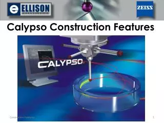
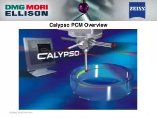
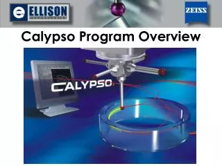
The Calypso Free Form Option is used to evaluate 3-D sections of a part. Free Form uses a CAD model to create a scan path, then gather data from the actual part. Using a Profile characteristic, we can compare the CAD model and the actual measured data to analyze the part.
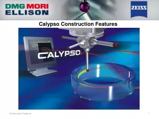
Free Form Surface features look and operate just like any other feature or characteristic in Calypso. They are represented as icons in the Feature List and follow the typical Calypso programming structure that all Calypso users are familiar with.
Some parts that can utilize Free Form may be difficult to align using the Standard Method (Spatial and Planar Rotation, X Y Z Origins) so a 3-D Best Fit method can be used. To do this, Space Points can be created on the CAD model, then added into a list of alignment features to help Calypso establish the part’s location on the CMM table. Here are a few examples of the space points used in 3-D Best Fit Alignments.
In the 3D Alignment screen, we pull in all of our space points taken from the CAD model. We can also choose to Loop our alignment to ensure that the part aligns properly. Break conditions can be applied once a required maximum deviation is met.
To establish a scan path for the Free Form feature, we open the feature’s strategy and click the “Define Points” button. This brings us to the “Generate Space Points” screen where we can create our scan path using one of five options: • Four Points • Line • Selection • From Curve(s) • From Face(s)
Option “Four Points” allows the user to click four points on the CAD model. Calypso then fills in the space between these four points with columns of points to be scanned. Users can define the number of columns in their scan path.
Option “Line” allows users to click two points on the CAD model. Calypso draws a line through these two points and creates a scan path. This is similar to a Curve feature.
Option “Section” allows users to click and drag in the CAD window, creating a section cut through the CAD model. The result is similar to the “Line” option shown earlier.
Option “From Curve(s)” puts the CAD window into wire-frame mode where users are able to select one or several edges from the CAD model. The result is a scan path along the selected edges.
Option “From Face(s)” allows users to select one or more faces from the CAD model. Calypso then fills in a scan path consisting of rows and columns on the selected surfaces. The number of rows and columns can be edited.
Here you can see the effect of increasing the number of columns from ten to twenty. As you can see, we will attain greater accuracy and more information from the scan path with twenty columns versus the scan path with only ten columns. This can be used with the “Four Points” or “From Face(s)” method.
Additionally, users can click the CAD model with the Strategy window open to define individual probing points. These points can then be converted into a scan path by highlighting all points and clicking the “Single Points / Auto Path Switch” button.
A Profile characteristic is used to evaluate and visualize free form features (Form and Location > Profile). These work exactly the same as other Calypso characteristics and utilize an “envelope” tolerance around the nominal CAD model. The actual deviations of the part can be viewed in several ways using the CAD Display Results.
Profile characteristics of Free Form features can also be evaluated without a datum structure in order to Best Fit the surface. The part pictured is shown referenced to the Base Alignment on the left and with no datum structure (Best Fit) on the right.
If you have any specific questions about how Freeform works, or would like confirmation that Calypso with Freeform is a good solution to your measurement challenges, please contact us! Ellison Technologies Southeast 4345 Morris Park Dr. Charlotte, NC 28227 704 545 7362