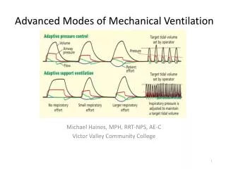
DT-1200 ADVANCED MECHANICAL DRAFTING
DT-1200 ADVANCED MECHANICAL DRAFTING. LECTURE #11. POSITION Controls locations of mating features. IDEAL CONDITION. UNACCEPTABLE CONDITION. ACCEPTABLE CONDITION. AXIS. CENTER PLANE. POSITION ZONE TYPES. Zones are located from datums with basic dimensions

DT-1200 ADVANCED MECHANICAL DRAFTING
E N D
Presentation Transcript
DT-1200ADVANCED MECHANICAL DRAFTING LECTURE #11
POSITION Controls locations of mating features IDEAL CONDITION UNACCEPTABLE CONDITION ACCEPTABLE CONDITION
AXIS CENTER PLANE POSITION ZONE TYPES • Zones are located from datums with basic dimensions • Zone sizes are specified in feature control frames • Zone is round (Ø) when it locates an axis (hole, post,) • Zone is flat (no Ø) when it locates a center plane (slot, tab) • Zone size may be modified (,) when dependent on feature size
POSITION TOLERANCE ZONE FOR HOLES IDEAL HOLE LOCATION = CENTER OF ZONE ACTUAL HOLE AXIS MUST LIE INSIDE ZONE HOLE AT TRUE POSITION ACCEPTABLE LOCATIONAL VARIATION ACCEPTABLE ANGULAR VARIATION
FIXED and FLOATING fasteners TWO CLEARANCE HOLES ONE CLEARANCE HOLE FLOATING FIXED
TOLERANCE = MMC CLR HOLE – MMC FASTENER 2 CALCULATING POSITION TOLERANCE WHEN USING FASTENERS MMC = largest screw & smallest clearance hole FLOATING FASTENER CONDITION TOLERANCE = MMC CLR HOLE – MMC FASTENER FIXED FASTENER CONDITION
DETERMINING MMC SIZES OF HOLES & FASTENERS FOR CALCULATIONS Fact #1 - Fastener companies manufacture screws so that their NOMINAL SIZES are at MMC (worst case is nominal size) RULE #1 The MMC of a fastener is its nominal size Fact #2 – Drill bits create holes that are always larger than their NOMINAL SIZES (worst case is nominal size for calculations) RULE #2 The MMC of a drilled hole is its nominal size
CLEARANCE HOLE NO CLEARANCE ADDITIONAL CLEARANCE FASTENER The MMC modifier The MMC modifier provides bonus tolerance whenever the tolerance zone size is based on the feature size Allowable movement of hole with hole at MMC Enlarged hole provides for more movement of hole ZONE SIZE CAN INCREASE
MMC question If feature size deviates from MMC, can the feature move farther out of position and still function correctly? If answer is “yes”, belongs in feature control frame
Ø.3970 (X) THRU Example – call out hole for 3/8” screw in fixed condition Nominal size of 3/8” screw is 3/8” (Ø.375) Clearance hole for 3/8” screw is made with drill bit “X” (Ø.3970) TOLERANCE ZONE DIAMETER = (.397 - .375) ÷ 2 = .011 ON THE DRAWING • Establish datums • Locate tolerance zone • Define hole and zone
.505 .497 2XØ THRU Calculating Actual Zone Size in Inspection Actual Zone Size = MMC zone size + feature size deviation from MMC MMC of hole = .497
The MMC modifier is a powerful tool for allowing bonus tolerance in the location of a feature without decreasing its function or quality Bonus tolerance = faster manufacturing time = less manufacturing cost = MORE MONEY FOR YOU
YOKE FORGING Phantom lines indicate areas where extra material will be machined off Dimensions reflect finished features