Download
1 / 77
990 likes | 1.68k Vues
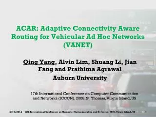
Vehicular Ad-hoc NETwork (VANET). Speaker: Yi-Ting Mai Contact info. :wkb@wkb.idv.tw Date: 2010/05/04. Outline. Overview of VANETs Physical Layer and MAC protocols for VANETs Broadcast Routing Protocols for VANETs Applications for VANETs. Why Vehicular Networks?. Safety

E N D
Vehicular Ad-hoc NETwork (VANET) Speaker: Yi-Ting Mai Contact info. :wkb@wkb.idv.tw Date: 2010/05/04
Outline • Overview of VANETs • Physical Layer and MAC protocols for VANETs • Broadcast Routing Protocols for VANETs • Applications for VANETs
Why Vehicular Networks? Safety On US highways (2004): 42,800 Fatalities, 2.8 Million Injuries ~$230.6 Billion cost to society Combat the awful side-effects of road traffic In the EU, around 40,000 people die yearly on the roads; more than 1.5 millions are injured Traffic jams generate a tremendous waste of time and of fuel Most of these problems can be solved by providing appropriate information to the driver or to the vehicle
Why Vehicular Networks? (cont.) Efficiency Traffic jams waste time and fuel In 2003, US drivers lost a total of 3.5 billion hours and 5.7 billion gallons of fuel to traffic congestion Profit Safety features and high-tech devices have become product differentiators
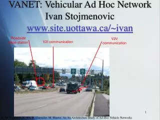
Inter-vehicle communication (IVC) Systems IVC systems are completely infrastructure-free; only onboard units (OBUs) sometimes also called in-vehicle equipment (IVE) are needed.
IVC systems Single-hop and multihop IVCs (SIVCs and MIVCs). SIVC systems are useful for applications requiring short-range communications (e.g., lane merging, automatic cruise control) MIVC systems are more complex than SIVCs but can also support applications that require long-range communications (e.g., traffic monitoring)
IVC systems a) Single-hop IVC system b) Multihop IVC system
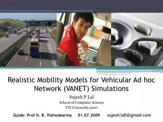
Vehicular Communication Future Vehicular Communication Scenario
Vehicular Communication-DSRC • In 2003, FCC established the service and license rules for Dedicated Short Range Communications (DSRC) Service. • DSRC is a communication service that uses the 5.9 GHz band (5.850-5.925 GHz band) for the use of public safety and private application. • The vehicular related services and communication standards enable vehicles and roadside beacons to form VANETs (Vehicular Ad Hoc Networks) in which the mobile nodes (vehicles) can communicate each other without central access points.
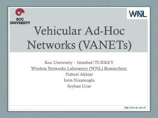
VANETs vs. MANETs • A VANET consists of vehicles to form a network which is similar to a Mobile Ad Hoc Network (MANET). However, there are following differences between these two networks. • Vehicles mobility • Vehicles move at high speed but mobility is regular and predictable • Network topology • High speed movement makes network topology dynamic • No significant power constraint • Recharging batteries from vehicle • Localization • Vehicles position estimate accurately through GPS systems or on-board sensors
Features of VANETs • The characteristics of VANETs can be summarized after comparing with the MANETs. • Dynamic topology • Nomadic nodes with very high speed movement cause frequent topology variation • Mobility models • Vehicles move along original trajectories completely different from typical MANET scenarios • Infinite energy supply • Power constraint can be neglected thanks to always recharging batteries • Localization functionality • Vehicle can be equipped with accurate positioning systems (GPS and GALILEO) integrated by electronic maps
Operating Environment • According to the environments of operating vehicles, the VANETs can be established in the following situations: • City environments, disaster situations, extreme weather conditions, and so on. • For instance: City environments, have certain unique characteristics: • Many tall buildings obstructing and interfering the transmission signals, • In the highway scenario, vehicles are closer together than, thus incur interference if their transmission range are large, • The topology is usually two dimensional (e.g. with cross streets).
Scopes of VANETs (1/2) • Communication range of VANETs • Short/medium-range communication systems (vehicle-to-vehicle or vehicle-to-roadside) • Applications of VANETs • The VANETs vision includes vehicular real-time and safety applications, sharing the wireless channel with mobile applications from a large, decentralized array of commercial service providers. • VANET safety applications include collision and other safety warnings. • Non-safety applications include real-time traffic congestion and routing information, high-speed tolling, mobile infotainment, and many others.
Scopes of VANET (2/2) • VANET research issues • Safety and non-safety applications • Roadside-to-vehicle and vehicle-to-vehicle communication • Communication protocol design • Channel modeling • Modulation and coding • Power control and scalability issues • Multi-channel organization and operation • Security issues and countermeasures • Privacy issues • Network management • Simulation frameworks & real-world testbeds
Threat model Presented in SeVeCom (Secure Vehicular Communication) project An attacker can be: Insider / Outsider Malicious / Rational Active / Passive Local / Extended Attacks can be mounted on: Safety-related applications Traffic optimization applications Payment-based applications Privacy
Attack 1 : Bogus traffic information Traffic jam ahead • Attacker: insider, rational, active
Attack 2 : Generate “Intelligent Collisions” SLOW DOWN The way is clear • Attacker: insider, malicious, active
Attack 3: Cheating with identity, speed, or position Wasn’t me! • Attacker: insider, rational, active
Protocols of Layers in VANETs • In this topic, we introduce the physical layer and the 802.11 related MAC protocols. Afterwards, the routing protocols between vehicles are presented.Finally, the applications of VANETs are proposed. • The physical layer and the 802.11 related protocols. • The physical layer and the MAC layer of DSRC/802.11p • 802.11 DCF • Routing protocols • Position-based Routing (Unicast) • Geocasting Routing (Multicast) • Broadcast Routing • Applications of VANETs.
Physical/MAC Layers • DSRC/802.11p • Dedicated Short Range Communication (DSRC) was released in 2002 by the American Society for Testing and Materials (ASTM). • In 2003, the standardization moved to IEEE Forum and changed the name from DSRC to WAVE (Wireless Ability in Vehicular Environments), which was also known as 802.11p.
DSRC/802.11p Physical Layer (1/4) • DSRC/802.11p • The standard of 802.11p is based on IEEE 802.11a PHY layer and IEEE 802.11 MAC layer • Seven 10 MHz channels at 5.9GHz • one control channel and six service channels
DSRC/802.11p Physical Layer (2/4) • DSRC/802.11p vs. 802.11a • 802.11a is designed for high data rate multimedia communications in indoor environment with low user mobility. • DSRC PHY uses a variation of OFDM modulation scheme to multiplex data. • high spectral efficiency, simple transceiver design and avoids multi-path fading
DSRC/802.11p Physical Layer (3/4) • DSRC/802.11p vs. 802.11a • DSRC/802.11p reduces the signal bandwidth from 20MHz to 10MHz. • all parameter values are doubled in time domain in order to increase the robustness (e.g. timeout increase) to ISI caused by the multi-path delay spread and Doppler spread effect • Data rates are between 6 and 27 Mbps • Transmit power level are changed to fit requirements of outdoor vehicular communications • communication ranges up to 1000 meters
Revolution and Design in 802.11 DCF • The revolution of 802.11 DCF can be described in the following. • The design of avoiding collisions: The design to solve the collisions including collisions incurred by the terminal problem. • The improvement design to IEEE 802.11 DCF
The Design of Avoiding Collisions • The design of avoiding collisions • In mobile wireless networks, the objectives of MAC protocols is to avoid collisions, process contention, and re-tramsit lost packets to increase the overall throughput. In previous works, the design of avoiding collisions can be described in the following. • Carrier Sense Multiple Access Protocols, CSMA: A mobile node uses carrier sensing technology to detect whether there is any node using the channel before transmitting data to avoid collisions. • The problems in the CSMA: hidden- and exposed- terminal problems • Terminal problems: • Hidden terminal problem • Exposed terminal problem
Medium Access Control (MAC) • LAN(Ethernet) • CSMA/CD(Carrier Sense Multiple Access with Collision Detection) • WLAN(802.11) • CSMA/CA (Carrier Sensing Multiple Access/Collision Avoidance)
CSMA/CD • CSMA/CD(Carrier Sense Multiple Access/ Collision Detection)
CSMA/CA • CSMA/CA(Carrier Sense Multiple Access/ Collision Avoidance)
A B C Hidden-Terminal Problem • The hidden-terminal problem occurs when node C sends data to node B, as shown in the following Figure.
A C D B Exposed-Terminal Problem • The exposed-terminal problem occurs when node C is exhibited to transmit data to node D. (Interfere) Broadcast ranges of each node
CSMA/CA (cont.) ACK
The Designs to Solve the Hidden-Terminal Problem • The Designs to Solve the Hidden-Terminal Problem • The design of using busy tone channel • The design of MACA (IEEE 802.11 DCF)
The Design with Busy Tone Channel • Protocol • Each node equipped with an extra busy tone channel to send out the busy signals when the node is processing data transmission. • When a node would like to transmit data, it detects weather there are nodes issuing the signals by other nodes in its range. • If a node detects no signal, it can process the transmission. • Problems • Needed an extra busy tone channel. • The hidden-terminal is solved, but the exposed-terminal problem still exists.
IEEE 802.11 DCF • To solve the hidden-terminal problem, MACA proposed the Multiple Access Collision Avoidance protocol, which is adapted by the IEEE 802.11 MAC to be the IEEE 802.11 DCF. • Contention period • Handshake period • Data period • ACK period
Contention Period of IEEE 802.11 DCF • Contention period • Interval Frame Space, IFS • Short IFS, SIFS):CTS, ACK, or Poll Response • PCF (PIFS) • DCF (DIFS)
Handshake period of IEEE 802.11 DCF • Handshake period • In MACA, before processing data transmission, a sender broadcasts a RTS (Request To Send) signal to inform its neighbors that it will send out data. • When a neighbor except the sender and the receiver receives the RTS signal, it use the NAV (Network Allocation Vector) to exhibit itself to issue signals to avoid occurring interference of data transmission. • When the receiver receives the RTS, it will reply a CTS (Clear To Send) signal if it accepts the RTS request. • Similarly, when a neighbor of the receiver except the sender receivers the CTS, it uses the NAV to exhibit itself to send any signal.
Data and ACK Periods of IEEE 802.11 DCF • Data period • After completing the handshaking period, the sender and the receiver can transit data, while the neighbors of these two nodes are exhibited by the NAV until the finishing data transmission. • ACK period • After the completion of data transmission, the receiver sends a ACK to the sender to show that the data has been received. • At the same time, all neighbors are in the listening status for contending the channel.
IEEE 802.11 DCF and Problems • With the protocol (IEEE 802.11 DCF) mentioned above can solve the hidden-terminal problems • The problems of IEEE 802.11 DCF • The exposed-terminal problems exists. • The number of contention nodes during the contention period increases. • The length of backoff time period.
Exposed-Terminal in IEEE 802.11 DCF • With IEEE 802.11 DCF, the nodes are exhibited by NAV increase. Therefore, the problem of exposed-terminal becomes more serious than CSMA. • In CSMA, only node C is exhibited to send or receive data. • In IEEE 802.11 DCF, nodes C and D are exhibited. (a) (b)