The GNU in RADIO
780 likes | 957 Vues
The GNU in RADIO. Shravan Rayanchu. SDR. Getting the code close to the antenna Software defines the waveform Replace analog signal processing with Digital signal processing Why? Flexibility, time to market, reliable Its all about the stack : GPRS/ WiFi / WiMax. SDR.

The GNU in RADIO
E N D
Presentation Transcript
The GNU in RADIO Shravan Rayanchu
SDR • Getting the code close to the antenna • Software defines the waveform • Replace analog signal processing with Digital signal processing • Why? • Flexibility, time to market, reliable • Its all about the stack : GPRS/ WiFi / WiMax
SDR • Possibilities …? • TX/RX on multiple channels simultaneously • Better spectrum usage • “Cognitive radios” • Disadvantages • Higher power consumption (GPU vs ASIC) • More MIPS! • Higher cost (as of today)
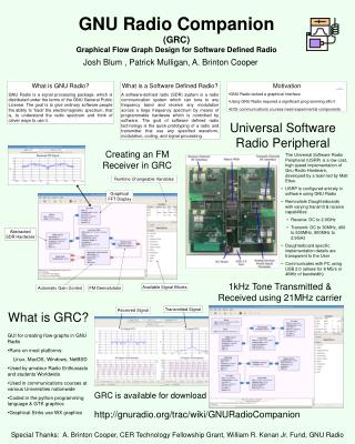
GNU RADIO • Platform for • Experimenting with digital communications • Signal processing using commodity hardware • Free software! • http://www.gnu.org/software/gnuradio/
ADC • Sampling Rate • Rate at which you sample the analog signal • Determines what frequency can be handled • Dynamic range • Number of signal levels • Quantization error • SNR = 6.02N + 1.76dB
Sampling Sum of sinusoids: Sigma ai Sin (2 pi fit)
Sampling Sin (2 pi fc nts) = Sin (2 pi fc nts+ 2 pi m) = Sin (2 pi nts (fc + m/n fs)) fc + k fs We need a LOW PASS FILTER !
Nyquist Criteria Sampling freq > Twice the max. frequency component in the signal of interest
ALIASING • ADCs in USRP: • 64 Msps 32 Mhz • How to receive 2.4 Ghz ? • RF Front end
RF Front End: Down conversion LPF ADC LPF Intermediate Frequency (IF) VCO Mixer: sinusoid of (RF-IF)
RF Front Ends • 50 - 860 Mhz RX • 400 – 500 Mhz Transceiver • 400 – 500 Mhz Transceiver • 400 – 500 Mhz Transceiver • 2300 – 2900 Mhz Transceiver • Bandpass filter (2.4 to 2.483 Ghz)
USRP • Universal Software Radio Peripheral • To rapidly design powerful, flexible software radio platforms • What does it have? • FPGA (ALTERA Cyclone) • Mixed signal processor (AD 9862) • Slots for 4 daughter boards (2 TX, 2 RX)
Boot sequence: two programmable components • USB Controller (Cypress FX2): 8051 code • FPGA (ALTERA Cyclone): Verilog
USRP • Four 12-bit ADC, 64 Msps • Sub-multiples are also possible: 42.66 Msps, 32 Msps, 25.6 Msps and 21.33 Msps • Decimation helps • IF has to be < 32 MHz • Four 14-bit DAC 128 Msps • Max. output 50 Mhz • Four I/Os simultaneously if we use real sampling, Two I/Os for complex sampling; synchronized clocks • Each daughter board has access to 2 DACs and 2 ADCs • Why Different boards ? • different RFs same IF
USRP • Four Digital Downconverters (DDCs) • FPGA with CIC Filters • Programmable decimation rate • Low pass filter • Two Digital Upconverters (DUCs) • AD 9862 • Programmable interpolation rate • USB 2.0 (480 Mbps, peak)
TX PATH AD 9862 Block D: The "Fine Modulator" -- this is a digital up-converter Block C: Interpolation filter (we interpolate by 4 in the AD9862) Block B: The "Coarse Modulator" Block A: The actual DACs.
GNU Radio Software Architecture • Library of signal processing blocks (C++) • Ex: sources, sinks, others • Input, output ports, types, ‘work function’ • Create a ‘flow graph’ : vertices are blocks and edges represent the data flow (Python) • SWIG, FFTW, Boost …
6 Mhz Limit • USB 2.0 limit 32 MBytes/sec • ADC 64 Msps 32 Mhz chunk • 8 Msps w/ 16 bit I/Q samples • 8 * 2 * 2 = 32 Mbytes/sec • 4 Mhz * 2 = 8 Mhz (Quadrature sampling) • Discard 1/4 of bins ~ 6 Mhz • Decimation (8, 256) • Interpolation (16,256)
Spectrum Sensing Tune : 0.001 sec , Dwell : 0.1 sec , Step: 0.5 Mhz , FFT : 1 Mhz wide
Spectrum Sensing Tune : 0.001 sec , Dwell : 0.1 sec , Step: 1 Mhz , FFT : 1 Mhz wide
Spectrum Sensing Tune : 0.001 sec , Dwell : 0.01 sec , Step: 1 Mhz , FFT : 1 Mhz wide
Spectrum Sensing Tune : 0.001 sec , Dwell : 0.01 sec , Step: 1 Mhz , FFT : 1 Mhz wide