Download
1 / 20
200 likes | 240 Vues
Explore the advancements in GDI engine design, fuel injection systems & fluid mechanics for high-performance internal combustion engines. Learn about GDI technology, cylinder flow optimization, and power output.

E N D
Next Generation SI Engines : GDI Internal Combustion Engines P M V Subbarao Professor Mechanical Engineering Department I I T Delhi New & Better Anatomy of Artificial Horse …..
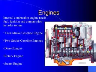
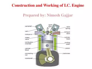
Geometry of Cylinder &In-cylinder Flow • Carburetor Era : Flat piston & Flat Cylinder --- Wedge shaped cylinder with flat piston. • SPI & MPI Era : Wedge shaped cylinder head --- special manifold for generation more turbulence – Optimized location of spark plug. • GDI Era : To design entire cylinder, piston and manifold geometry using computational and experimental fluid mechanics. • More the use of Fluid Mechanics, the better will be the engine. • Three dimensional turbulent flow simulation will be culmination of IC Engine Development.
High End Automobiles with GDI I.C. Engine • 1999 Mitsubishi Mirage 1500 GDi Dingo Pearl : Naturally aspirated petrol Engine Inline 4 cyl.1468 cc : DOHC : 16 valves : 78 kW@ 6000 :140 Nm at 3500 rpm : CR=11:1. • BMW Z4/528i:Twin Power Turbo Inline 4 cyl. 16 Valve: 1997CC: 180kW@ 5000rpm: 10.0 : Fuel economy: 5.9/8--/8.8 l/100km. • 2017 Kia Sportage SX Turbo 2.4L : In-line 4 cyl. DOHC GDI- D-CVVT 16 valve : 2,359CC : 135kW @ 6,000rpm: 237Nm@4000rpm : CR=11.3 : Fuel economy: 6.7/8.5/11.8 l/100km.
In-Cylinder Flow Geometry of A GDI Engine • Injection of gasoline directly inside the cylinder at high pressure. • Enhanced evaporation and mixing are facilitated through turbulent flow inside the cylinder. • Can generate homogeneous or stratified mixture. • Ultra lean mixtures can be used. A Comprehensive use of Advanced Fluid Mechanics in the design and development of IC engines.
Objectives for the development of GDI engine • Very high fuel economy • Superior power output than MPFI engine • Acceptable levels of emissions GDI is basically a combination of CI & SI engines.
Superior output mode Injection in late intake stroke Wider spray with high penetration for charge homogenization A/F – Stoichiometric Homogeneous A-F Mixture Complete Vaporization of Fuel Ultra Lean combustion mode Very lean stratified mixture : A/F ~ 30 Injection during compression Compact spray, deflected from the piston top to the spark plug Distinct Stratification At spark , ignitable mixture conditions Operating modes of the GDI engine It is two engines in one place
Challenges in developing DGI Engine • The fuel injection to the cylinder should meet two requirements. • First one, it should enable the homogeneous charge burning. • Secondly, It should also enable obtaining a lean mixtures close to cylinder walls. • The injection system must allow for any quantitative and qualitative formation of the charge and affect the way it is later burnt. • The macroscopic characteristic of fuel injection spray like penetration and spray angle are crucial for the correct operation of the engine.
GDI : 50 – 100 bar Multi Poin Injection : ~ 5 bar Single Point Injection 2 – 3 bar Carburetor : 20 – 50 Pa Challenging Fluid Mechanics of Fuel Admission Injection Pressure Technology of Fuel Admission
GDI : 20 – 50 mm Multi Poin Injection : ~ 200mm Single Point Injection 100 – 300mm Carburetor : 1 ~ 3 mm Fluid Mechanics of Fuel Admission Droplet size Technology of Fuel Admission
GDI engine power MPI engines Carburetor GDI engine Fuel economy Diesel engine MPI engine Carburetor A/F ratio Performance of GDI
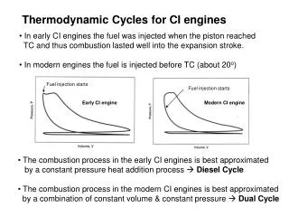
Thermodynamic Modeling : Development of Pseudo GDI Engine • Modeling of IC engine process can be carried out in many ways. • Multidimensional, Transient Flow and heat transfer Model. • Thermodynamic Transient Model USUF. • Fuel-air Thermodynamic Model. • Air standard Thermodynamic Model