Remote Control Helicopter
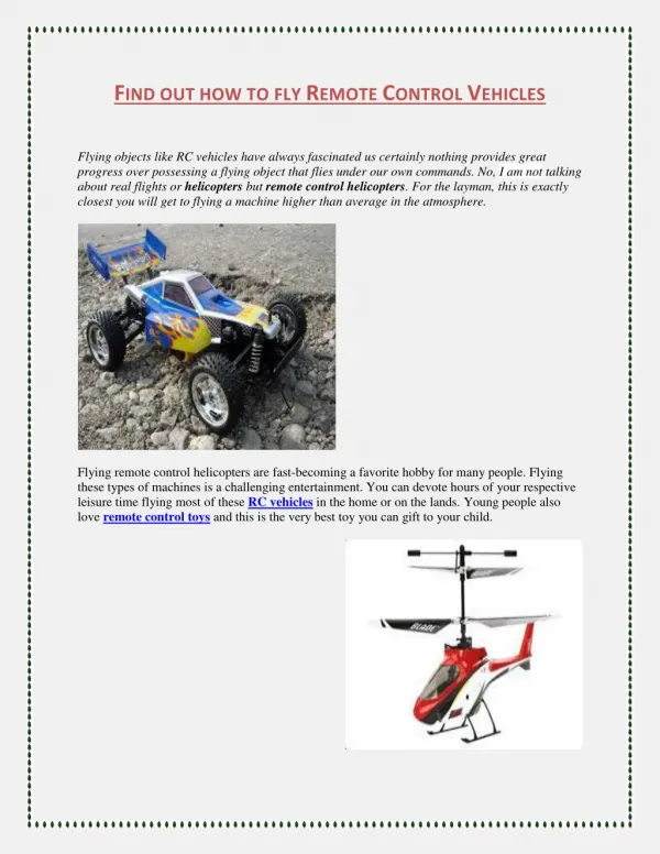
This project, undertaken by a team of aerospace enthusiasts, focuses on the dynamics of the RC Dragonfly helicopter. The members—Moiz Kapadia, Adam Golembeski, Eric Silk, and Paul DiFilipo—aim to deepen their understanding of helicopter mechanics, particularly lift generation, motion control, and key components such as the tail rotor and swash plate. The construction and modeling processes involved challenges like servo motor constraints and precise measurements. With teamwork and dedication, the project highlights both technical skills and the motivation to innovate in aerospace technology.

Remote Control Helicopter
E N D
Presentation Transcript
Remote Control Helicopter Group 9 Moiz Kapadia Adam Golembeski Eric Silk Paul DiFilipo
Motivation • A majority of the members are pursuing the aerospace option. • Interested to learn and understand the dynamics of a helicopter. • The RC Dragonfly posed as an appropriate challenge for 4 group members.
How the RC Dragonfly Works • Helicopters generate lift by creating a pressure differential across the blade • The motion of the swash plate regulates the forward, backward, left & right motion • Yaw is controlled by the speed of the tail rotor
How the RC Dragonfly Works con’t.. • Flybars work in conjunction with the swash plate to guide the roll & pitch • Servo motors control the motion of the swash plate • This is a fixed pitch model, meaning the main rotors are rigid to the shaft.
Major Components • Battery Tray • Tail Rotor • Main Chassis and Landing Gear • Main Rotor • Swash Plate • Body
Battery Tray • Mirror, extrude, and cut. • Basic constraints such as axis align, datum plane offset and mate was used.
Tail Rotor • Revolve, extrude, mirror, shell methods were implemented in modeling. • Pin connections. • Gear connections made in mechanism mode
Chassis and Landing Gear • Mirror, extrude, cut, sweep protrusions. • Axis align, datum plane offset, and mate. • Intricate angles were measured to fully constrain the landing gear and support beams
Main Rotor • Contains complex series of constraints including pin, bearing and ball joint. • Simple methods of modeling such extrude, cut and mirror were implemented.
Helicopter Body • Outlined digital pictures of body with Style Tool, Mirror, Shell, and Extrudes to model the main body. • Cut out of windshield, color, and reassemble.
Problems Encountered • Constraining servo motors • Replicating swash plate movement • Parts needing to be re-measured • Unit corrections
Thank you Ray for all your help & motivation this semester. Thank You