MCWF Toroidal Joint Concerns
This report examines the friction coefficient required to prevent slipping in Toroidal Joints, crucial for maintaining structural integrity within the NCSX criteria. Analysis indicates a need for a minimum coefficient of friction exceeding 0.3, particularly in unbolted inboard regions. The study evaluates the impact of joint stiffness and bolt preload, while assessing the effects of allowing the inner leg to slip. The findings raise questions regarding achievable friction levels and the influence of the TF structure on joint rigidity. Further investigations and a composite model may be warranted.

MCWF Toroidal Joint Concerns
E N D
Presentation Transcript
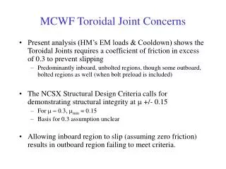
MCWF Toroidal Joint Concerns • Present analysis (HM’s EM loads & Cooldown) shows the Toroidal Joints requires a coefficient of friction in excess of 0.3 to prevent slipping • Predominantly inboard, unbolted regions, though some outboard, bolted regions as well (when bolt preload is included) • The NCSX Structural Design Criteria calls for demonstrating structural integrity at m +/- 0.15 • For m = 0.3, mmin = 0.15 • Basis for 0.3 assumption unclear • Allowing inboard region to slip (assuming zero friction) results in outboard region failing to meet criteria.
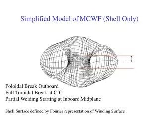
Identification of Shim Segments used for Force Summations ab2tl ab2tru aatl bc2tru bc2tl aatr cc2t ab2trl bc2trl aain cc2in ab2in bc2in bc2bru ab2br aabr cc2b bc2brl aabl bc2bl ab2bl -60 deg 0 deg bctl abtl bctru cct abtr bctrl bcin ccin abin bctrl abbru ccb bcbl abbrl bcbrl abbl +60 deg Green Regions (*in) unbolted
Baseline Analysis Shows IL wants to Slip CC BC AB AA AB BC CC Data counter-clockwise within block, ending at inner leg
Letting IL Slip Causes More Slipping in Neighboring Regions CC BC AB AA AB BC CC
Slipping Slightly Worse(?) when Freely Supported CC BC AB AA AB BC CC
Notes • Cases run letting the Inner Leg slip are Linear analyses: • Softened out-of-plane shear modulus • Conductor bonded to MCWF • Wings not bonded (free) • Analyses run without bolt preload • Effect of preload added afterwards • Assumes 45797 #/bolt at 80K and joint stiffness ratio kb/(kb+km) = 0.118 • MCWF Structure Only included • How will inclusion of TF structure impact MCWF joints? • Test Cases run with rigid constraints (more than can be achieved)
Test Case Constraining MCWF Top and Bottom in z and theta The best we can do to stiffen MCWF – but not achievable
Test Case Constraining MCWF Top and Bottom in z and theta CC BC AB AA AB BC CC
Test Case Constraining MCWF Top and Bottom in z and theta CC BC AB AA AB BC CC
Summary • Need to understand what coefficient of friction can be achieved within Toroidal Joints • Is there any test data to support using .3 or possibly higher? • Do we need to consider other mechanisms for carrying shear? • Is the bolt at the limit for preload? If not, can other components also withstand more? • Including TF Structure may help rigidity a bit, but not likely to be enough. • Probably should still generate composite model if doable to remove uncertainties.