Advanced Mechanical System Modeling Solutions by LEDAS
420 likes | 557 Vues
LEDAS, established in 1999, specializes in creating computational components for software development in industries such as PLM, CAD, CAM, and CAE. This includes a state-of-the-art mechanical simulation engine featuring effective collision detection and resolution techniques. LEDAS empowers organizations through custom application development, training, and consulting. With a focus on automating design, simulation, and planning processes, LEDAS aims to accelerate product development in collaboration with leading CAD/CAM/CAE/PDM providers. Discover more at www.ledas.com.

Advanced Mechanical System Modeling Solutions by LEDAS
E N D
Presentation Transcript
LEDAS Solutions for Mechanical System Modeling and Related Problems Egor Ermolin (LEDAS)
Agenda • LEDAS Company • LEDAS Phoenix and Related Projects: • History • Mechanical simulation engine • Functionality • Architecture: Dynamic Engine, Collision Detection, Collision Resolution • Impulse-based Collision Resolution • Geometry: • Calculation of Dynamic Properties • Effective Collision Detection • Narrowing broad phase • Demos • Key Features • Development Perspective SBRAS/ Intel GeometrySeminar
LEDAS Company • Positioning • Mission • Competence • Customers • Isicad-2008 SBRAS/ Intel GeometrySeminar
Positioning of LEDAS • LEDAS Ltd. is an independent software development company founded in 1999 in Novosibirsk, Russia • Using proprietary mathematical technologies, LEDAS provides computational components and services for software development companies in the fields of PLM (including CAD, CAM, CAE, PDM) and ERP • The company also provides services for manufacturers: • Custom application development, integration & localization • Creation of 3D models using different CAD systems • Consulting, reselling, trainings • Information on LEDAS is available at www.ledas.com SBRAS/ Intel GeometrySeminar
Mission • We at LEDAS perceive our mission as the automation of key industrial processes – design, simulation and planning • These are areas where system users require a set of intelligent functions in order to accelerate product development and planning of related processes and resources • LEDAS does not develop end-user nor enterprise software, but it collaborates actively with both CAD/CAM/CAE/PDM software development companies andmanufacturing enterprises by offering them • Computational software components • Software development & 3D modeling • Consulting, reselling, training • Places where they can meet together CAD/CAM/CAE/PDM development company Development Marketing LEDAS Deployment Customization Manufacturing enterprise SBRAS/ Intel GeometrySeminar
Mathematics & Computer Science Numerical analysis Constraint satisfaction Computational geometry Scheduling algorithms Software Development Development Processes Quality Assurance Available platforms Programming skills Software tools CAD/CAM/CAE/PDM skills Creation of 3D models Custom application development Translation & localization Certified training Reselling Consulting Publishing & Conferencing Web sites Books Conferences LEDAS Competence SBRAS/ Intel GeometrySeminar
LEDAS Customers • Dassault Systèmes (France) • Development of core computational components for CATIA V5 products • Software localization for Russian market • Total cost of development projects is about 80 person-years since 1999 • Sukhoi Civil Aircrafts (Russia), AVTOVAZ (Russia), and others • Consulting & training on CATIA/CAA solutions • Custom software development (add-on applications for CATIA and NX) in the field of computational geometry, data translation and CAD application integration • Proficiency (Israel), ADEM Technologies (Russia), AWV (Switzerland), Tecnos (Italy), Evo.Solutions (Japan), and others • Licensees of LEDAS Geometric Solver (LGS) software components • Cooperation on integration of LGS into different CAD applications: sketcher, assembly design, data translation • Exigen (USA), CTRUE (Israel), and others • Development of advanced software packages based on LEDAS competence in optimization algorithms, resource scheduling, and computational geometry • VirtualCAD (Canada) • Creation of libraries of parametric 3D models and web-catalogues of CAD parts • Purdue Unviversity (USA), Novosibirsk Technical University (Russia) • Education & research SBRAS/ Intel GeometrySeminar
Isicad-2008 • Third international multi-vendor PLM forum • June 4-6, Novosibirsk, Russia • About 500 attendees representing large, medium and small manufacturing enterprises • More than 30 CAD, CAM, CAE, PDM solution providers • Autodesk, Siemens PLM, PTC and Dassault are traditional participants • All leading Russian CAD/PLM R&D companies • Leading Russian mass media • Multi-format • Invited talks • Plenary session talks • Technical section talks • Company’s seminar • Round table and press conference • Rich social program • More information at http://isicad.ru/2008 SBRAS/ Intel GeometrySeminar
We are here • LEDAS Company • LEDAS Phoenix and Related Projects: • History • Mechanical simulation engine • Functionality • Architecture: Dynamic Engine, Collision Detection, Collision Resolution • Impulse-based Collision Resolution • Geometry: • Calculation of Dynamic Properties • Effective Collision Detection • Narrowing broad phase • Demos • Key Features • Development Perspective SBRAS/ Intel GeometrySeminar
The Phoenix Project • The LEDAS Phoenix Project is oriented to a creation of competitive mechanical simulation engine with broad spectrum of applications SBRAS/ Intel GeometrySeminar
A Mechanical Simulation Engine • Modeling of 2D/3D rigid bodies motion according to physical laws • Modeling of forces with different nature • Gravity • Springs • Dynamically acting user-defined forces • Collision detection and resolution • Avoiding interpenetration • Motion modeling under geometrical constraints • Assembly constraints SBRAS/ Intel GeometrySeminar
Architecture Application Rigid bodies data Getting a geometrical data Getting/updating coordinates and velocities Getting a physical data Updating velocities Collision Detection Dynamic Engine Collision Resolution Passing list of colliding bodies Passing list of moved bodies Getting list of colliding bodies SBRAS/ Intel GeometrySeminar
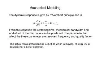
Uses simple explicit difference scheme Dynamic Engine • Models motion of rigid bodies with account of external forces • Gravity • Springs • Dynamically acting user-defined forces • Manages Collision Detection and Collision Resolution modules SBRAS/ Intel GeometrySeminar
Constraints based techniques for contact resolution • Penalty method • Impulse-based methods Collision Resolution • Collision Resolution is aimed to correct rigid bodies velocities in order to avoid interpenetrations • Known approaches Chosen approach SBRAS/ Intel GeometrySeminar
Impulse-based approachInitial assumptions • Basic assumptions • Collision time is infinitely small • Collision forces are infinitely large • Increments of impulses are finite • There are two phases of collision • Compression phase • Restitution phase • Total impulse obtained by a body during collision takes into account both phases: where is a coefficient of restitution, and impulse obtained during compression phase SBRAS/ Intel GeometrySeminar
Some definitions • Relative velocity at the point is calculated from first body to second: • Normal at collision point is taken from first body • Case scalar product : < 0 interpenetration point = 0 contact point > 0 leaving point SBRAS/ Intel GeometrySeminar
Consider contact points with negative normal relative velocities, such that bodies are penetrating • Consider contact points with negative normal relative velocities, such that bodies are penetrating • Assume that force acts in contact point • Assume that force acts in contact point • Express velocities of the bodies after a compression phase via unknown compression impulses Approach Overview • With known expressions for velocities express relative normal velocities of the bodies in the contact point SBRAS/ Intel GeometrySeminar
We can obtain compression impulses via SVD-method and full impulses passed between bodies due to collision in i-th point is Impulse-based approachLinear system • Condition of vanishing of the relative normal velocities at the end of the compression phase leads to the following linear mxm system of equations • After determination of the impulses we can compute new velocities of the bodies SBRAS/ Intel GeometrySeminar
Impulse-based approachIterative scheme • With known new velocities we should check other contact points for which initially no penetration occurred • If there are points in which the bodies are penetrating we repeat impulses computation for these new set of points • As practice showed this iterations are converged for e≤1 SBRAS/ Intel GeometrySeminar
Joints Handling • This approach can be used for a modeling of joints • Joint is modeled via three (or two for 2D) collision points with e=0 considered on each time step • On each time step relative velocities of the bodies in the joint point coincide • Impulses corrections have to be calculated from a condition of coordinates coincidence not velocities SBRAS/ Intel GeometrySeminar
We are here • LEDAS Company • LEDAS Phoenix and Related Projects: • History • Mechanical simulation engine • Functionality and applications • Architecture: Dynamic Engine, Collision Detection, Collision Resolution • Impulse-based Collision Resolution • Geometry: • Calculation of Dynamic Properties • Effective Collision Detection • Narrowing broad phase • Demos • Key Features • Development Perspective SBRAS/ Intel GeometrySeminar
From Dynamic to Geometry: Calculation Of Dynamic Properties • Given a manifold 3D triangular mesh, we can compute mass and inertia tensor properties of encapsulated volume • Mirtich in 1996 proposed to use divergence and Green’s theorems to reduce complex 3D integral to line integrals: SBRAS/ Intel GeometrySeminar
Collision Detection • Broad phase: test collision for only for bodies which have bounding primitives intersecting • Solution: encapsulate objects by simple shells with inexpensive intersection test • Optimization of this phase: don’t check intersection for shells that obviously don’t intersect (rule?) • In 2D prototype implementation we use pair-wise check on broad phase using circles as bounding primitives SBRAS/ Intel GeometrySeminar
Collision Detection • Narrow phase: pair-wise element check – test each geometry primitive of one body with each another’s • Various space partitions can be applied to reduce number of pairs to check • In 2D prototype implementation we use direct check of all pairs • Detects collisions and returns coordinates of a contact points and normal vectors • It supports line segments and arcs as geometry primitives and uses direct collision detection with rejection of bodies which are situated far apart SBRAS/ Intel GeometrySeminar
Collision Detection 3D Implementation • Based on OBB-approach (inertia axis) in narrow phase, collision detection library OPCODE 1.3 is used for reference. Current implementation consumes less memory than OPCODE (about 10%), but is 1.7 times slower*. However, performance optimization was not the objective • Broad phase uses O(n2) pairwise OBB-comparison. This stage can be optimized up-to O(nlogn) comparison (in practice O(n)), but even this is not top of high-performance… * Data is based on LEDAS collision detection report (in Russian) SBRAS/ Intel GeometrySeminar
Collision Detection: narrowing broad phase • The problem is that OBB is usually better heuristics of bounding volume than AABB (in terms of volume), but it is not minimal bounding box for body in general case • Which pattern better fits the broken window? AABB OBB Minimal BB • The advantage is obvious: the less volume BB has, the less number of false narrow phase triggering will happen SBRAS/ Intel GeometrySeminar
Finding Minimal Boxes: LEDAS Implementations • 2D case only requires body to be convex, algorithm is quite straightforward and can be described by “rotating calipers” model • 3D case also operates on convex mesh and involves Gaussian sphere structure to test configuration. It requires polynomial trigonometric equation solver to find minimum of volume function SBRAS/ Intel GeometrySeminar
Computational effectiveness of BB • Conclusion: minimal BB can be used in applications which allow preprocessing and require maximum performance or have scenes with great number of objects SBRAS/ Intel GeometrySeminar
We are here • LEDAS Company • LEDAS Phoenix and Related Projects: • History • Mechanical simulation engine • Functionality and applications • Architecture: Dynamic Engine, Collision Detection, Collision Resolution • Impulse-based Collision Resolution • Geometry: • Calculation of Dynamic Properties • Effective Collision Detection • Narrowing broad phase • Demos • Key Features • Development Perspective SBRAS/ Intel GeometrySeminar
Demos Unstable stack SBRAS/ Intel GeometrySeminar
Demos Domino effect SBRAS/ Intel GeometrySeminar
Demos Springs SBRAS/ Intel GeometrySeminar
Demos Telescopic mast SBRAS/ Intel GeometrySeminar
Demos Door latch SBRAS/ Intel GeometrySeminar
Demos Engine SBRAS/ Intel GeometrySeminar
Demos Jib SBRAS/ Intel GeometrySeminar
Demos 3D Collision SBRAS/ Intel GeometrySeminar
Industrial Application • Integration of Minimal Bound Box solution into CATIA (customer SCAC) is in process • At LEDAS convergence of BB code is performed SBRAS/ Intel GeometrySeminar
We are here • LEDAS Company • LEDAS Phoenix and Related Projects: • History • Mechanical simulation engine • Functionality and applications • Architecture: Dynamic Engine, Collision Detection, Collision Resolution • Impulse-based Collision Resolution • Geometry: • Calculation of Dynamic Properties • Effective Collision Detection • Narrowing broad phase • Demos • Key Features • Development Perspective SBRAS/ Intel GeometrySeminar
Key Features of Phoenix Project • Approach doesn’t need decomposition of bodies into convex parts • Absolute elastic (energy-preserving) and inelastic adjustability • Native support of geometrical constraints • Collision detection in 3D with near-industrial characteristics is ready • If preprocessing allowed, bounding volumes can be very tight SBRAS/ Intel GeometrySeminar
Implementation Summary • 2D dynamic engine with segment-arc geometry, resolves collision, supports springs and joints • Computation of mass and inertia properties for triangular mesh • 3D dynamic engine based on triangular meshes OBB collision detection • 3D convex hull module (Preparata’s divide-and-conquer) • Module for calculating minimal bounding box for triangle mesh SBRAS/ Intel GeometrySeminar
Development Perspective • We have advanced results in mechanical modeling and computational geometry related problems • Some of our implementations already have applications, but our solutions have much greater potential • Thus we are looking for partner/customer to bring our ideas to life SBRAS/ Intel GeometrySeminar