MESB 374 System Modeling and Analysis Translational Mechanical System
MESB 374 System Modeling and Analysis Translational Mechanical System. Translational Mechanical Systems. Basic (Idealized) Modeling Elements Interconnection Relationships -Physical Laws Derive Equation of Motion (EOM) - SDOF Energy Transfer Series and Parallel Connections

MESB 374 System Modeling and Analysis Translational Mechanical System
E N D
Presentation Transcript
MESB 374 System Modeling and AnalysisTranslational Mechanical System
Translational Mechanical Systems • Basic (Idealized) Modeling Elements • Interconnection Relationships -Physical Laws • Derive Equation of Motion (EOM) - SDOF • Energy Transfer • Series and Parallel Connections • Derive Equation of Motion (EOM) - MDOF
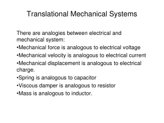
Key Concepts to Remember • Three primary elements of interest • Mass ( inertia ) M • Stiffness ( spring ) K • Dissipation ( damper ) B • Usually we deal with “equivalent” M, K, B • Distributed mass lumped mass • Lumped parameters • Mass maintains motion • Stiffness restores motion • Damping eliminates motion (Kinetic Energy) (Potential Energy) (Eliminate Energy ? ) (Absorb Energy )
Variables • x : displacement [m] • v: velocity [m/sec] • a: acceleration [m/sec2] • f: force [N] • p : power [Nm/sec] • w : work ( energy ) [Nm] 1 [Nm] = 1 [J] (Joule)
K Basic (Idealized) Modeling Elements • Spring • Stiffness Element • Reality • 1/3 of the spring mass may be considered into the lumped model. • In large displacement operation springs are nonlinear. Linear spring nonlinear spring broken spring !! • Idealization • Massless • No Damping • Linear • Stores Energy Hard Spring Potential Energy Soft Spring
x1 x2 x fD fD f2 M f1 B f3 Basic (Idealized) Modeling Elements • Damper • Friction Element • Mass • Inertia Element • Dissipate Energy fD • Stores Kinetic Energy
K,M x x M K M K Interconnection Laws • Newton’s Second Law Lumped Model of a Flexible Beam • Newton’s Third Law • Action & Reaction Forces Massless spring E.O.M.
Modeling Steps • Understand System Function, Define Problem, and Identify Input/Output Variables • Draw Simplified Schematics Using Basic Elements • Develop Mathematical Model (Diff. Eq.) • Identify reference point and positive direction. • Draw Free-Body-Diagram (FBD) for each basic element. • Write Elemental Equations as well as Interconnecting Equations by applying physical laws. (Check: # eq = # unk) • Combine Equations by eliminating intermediate variables. • Validate Model by Comparing Simulation Results with Physical Measurements
Vertical Single Degree of Freedom (SDOF) System xs x B,K,M B K f g x f M M M g • Define Problem The motion of the object • Input • Output • Develop Mathematical Model (Diff. Eq.) • Identify reference point and positive direction. • Draw Free-Body-Diagram (FBD) • Write Elemental Equations From the undeformed position From the deformed (static equilibrium) position • Validate Model by Comparing Simulation Results with Physical Measurement
x K M B Energy Distribution • EOM of a simple Mass-Spring-Damper System We want to look at the energy distribution of the system. How should we start ? • Multiply the above equation by the velocity term v : Ü What have we done ? • Integrate the second equation w.r.t. time: Ü What are we doing now ? f Change of kinetic energy Change of potential energy Energy dissipated by damper
Example -- SDOF Suspension (Example) • Simplified Schematic (neglecting tire model) • Suspension System Minimize the effect of the surface roughness of the road on the drivers comfort. From the “absolute zero” From the path From nominal position g M x K B x x p
x2 x2 x2 x1 x1 xj x1 Û fS fS fS fS K1 K1 K2 K2 KEQ fS Series Connection • Springsin Series fS
x2 x1 x2 x1 fD fD Series Connection • Dampersin Series Û fD fD BEQ B1 B2
x2 x1 x2 x1 K1 fS fS KEQ K2 Parallel Connection • Springsin Parallel fS fS Û
x2 x1 x2 x1 B1 fD fD fD fD BEQ B2 Parallel Connection • Dampersin Parallel Û
K K Horizontal Two Degree of Freedom (TDOF) System • DOF = 2 • Absolute coordinates • FBD K K • Newton’s law
K K Horizontal Two Degree of Freedom (TDOF) System Static coupling • Absolute coordinates • Relative coordinates Dynamic coupling
Two DOF System – Matrix Form of EOM K K Input vector • Absolute coordinates Output vector Mass matrix Damping matrix SYMMETRIC • Relative coordinates Stiffness matrix NON-SYMMETRIC
MDOF Suspension • Simplified Schematic (with tire model) • Suspension System TRY THIS x p
MDOF Suspension • Simplified Schematic (with tire model) • Suspension System Assume ref. is when springs are Deflected by weights Car body Suspension Wheel Tire Road Reference
FS2 FS1 FD1 FD2 x2 x1 FS2 FS2 FD2 FD2 FS2 FD1 FD2 FD2 FS2 M1 M2 FS1 Example -- MDOF Suspension • Draw FBD • Apply Interconnection Laws
Example -- MDOF Suspension • Matrix Form Mass matrix Damping matrix Stiffness matrix Input Vector