Download
1 / 5
50 likes | 141 Vues
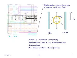
Shield walls – extend the length of channel – will ‘pull’ field. y. Coil. x. + 3.7m. ~ – 4.6m. Centred coil + 2 walls X – Y asymmetry Off-centre coil + 2 walls X (= L-R) asymmetry also Hard to estimate Need 3D field calculation with iron (mirrors).

E N D
Shield walls – extend the length of channel – will ‘pull’ field y Coil x + 3.7m ~ – 4.6m Centred coil + 2 walls X – Y asymmetry Off-centre coil + 2 walls X (= L-R) asymmetry also Hard to estimate Need 3D field calculation with iron (mirrors) PC 325
Looked here z = 5800mm (only place we looked) 3D Opera Observed A ~ 8% r=10mm A ~ 4% r= 20mm Xo ~ 0.4mm (need to check not ‘mesh effect’) 0.4mm doesn’t seem bad BUT 1) looked in region (5800mm) screened by current sheet 2) region between FC & CC not screened 3) CC is largest coil – r = 0.8m expect much larger effects ??? I am in contact with Jim R. He will re-run 3D calc. (had some incorrect J’s) & we shall look again at other z’s I expect big effects! TBC PC 325
3D Model of MICE + Hall shields and beams etc. (From Jim Rochford) Everything shown is either coil or ferromagnetic Compare field components Bx,By, Bz on axis with and without the iron Difference = Error field on axis PC 325
Bz on axis Flip Mode, 240 MeV/c Bx, By on axis (Gauss) 1G = 10-4 Tesla should = 0 Max Br ~ 34 G = 3 x 10⁻³ T Undoubtedly major effect from Coupling Coils at +/- 1.375m It takes ~ 24 hours to compute one set of 2700 points..... PC 325
Does this matter? A stupid calculation using error field alone gives ~20mm displacement for 200 MeV/c muon starting on axis Big problem (but dumb calculation) Various reasons to think it does / does not. Various reasons to think it does not. Need to track with a field map ! Problem – how to get field map in a finite time?? Possible Solution ‘Image Coils’ – but shield wall geometry is complicated To be continued PC 325