TRIGGERING IN THE ATLAS EXPERIMENT
540 likes | 705 Vues
TRIGGERING IN THE ATLAS EXPERIMENT. Thomas Sch örner-Sadenius UHH (formerly CERN EP/ATR) UHH, SS06. OVERVIEW. ¶ INTRODUCTION • The Large Hadron Collider (LHC) – Why? • Physics at the LHC • The ATLAS Experiment • The ATLAS Trigger. ¶ THE LEVEL1 TRIGGER (L1).

TRIGGERING IN THE ATLAS EXPERIMENT
E N D
Presentation Transcript
TRIGGERING IN THE ATLAS EXPERIMENT Thomas Schörner-SadeniusUHH (formerly CERN EP/ATR) UHH, SS06
OVERVIEW ¶ INTRODUCTION • The Large Hadron Collider (LHC) – Why? • Physics at the LHC • The ATLAS Experiment • The ATLAS Trigger ¶ THE LEVEL1 TRIGGER (L1) ¶ THE HIGH-LEVEL TRIGGER (HLT) ¶ TRIGGER PERFOMANCE STUDIES TSS: Triggering in ATLAS
THE LHC - WHY? Standard-Model (SM) well confirmed, but incomplete ! LEP, HERA, Tevatron … + SM precision measurements (QED, QCD, electroweak) … but openquestions: -- EW symmetry breaking?-- 25 free parameters?-- Unification?-- Discrepancy at sin2eff etc? LHC • Higgs bosons (SM/MSSM)• Supersymmetry• Large Extra Dimensions, Compositeness, new heavy gauge bosons• SM measurements, b physics TSS: Triggering in ATLAS
B0dK0* PHYSICS AT THE LHC I pp collisions with s = 14 TeV,L = 1034 cm-2s-1, f = 40 MHz SM Physics: SM Higgs: MSSM/SUSY: TSS: Triggering in ATLAS
PHYSICS AT THE LHC II Comparison of SM and ‘new physics’ processes Small cross-sections for‘new physics’processes … and small branching ratios (e.g. H).SM processes dominate. At high luminosity~23 events overlaid … for 2•1033cm-2s-1 usually only one event Understandingof SM processesimportant • Backgrounds for ‘discovery physics’: Wbb, ttbb, W/Z pairs…• Calibration, energy scale: Ze+e-,+-, J/e+e-,+-, Wjj… Necessity of efficient trigger! TSS: Triggering in ATLAS
ATLAS TRIGGER MENU COVERAGE Triggering mostly with inclusive / di-leptons. • Gauge boson pair production for study of anomalous couplings and behaviour of production at high energies • single and pair top production• direct Higgs production with HZZ*/WW*; associated SM Higgs production with WH, ZH, ttH• MSSM Higgs decays• Production of new gauge bosons with decays to leptons. • SUSY and leptoquark searches Inclusive anddi-lepton B physics • specialised, more exclusive menus H • 2EM15I at L1, 220i at L2. Also MSSM. SUSY,leptoquarks • High pT jets with/without ETmiss. Resonances,compositeness • High pT jets. TSS: Triggering in ATLAS
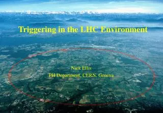
THE LHC pp at 14 TeV TSS: Triggering in ATLAS
THE LHC pp at 14 TeV TSS: Triggering in ATLAS
THE LHC pp at 14 TeV TSS: Triggering in ATLAS
THE LHC pp at 14 TeV TSS: Triggering in ATLAS
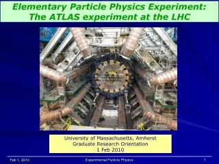
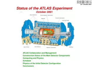
THE ATLAS EXPERIMENT - Length ~40 m- Diameter ~25 m- Weight ~7000 t- 108 channels (event ~2MB) - ‘Inner (tracking) Detector’- calorimeters (energies)- muon detectors - Barrel: solenoid around ID and toroid fields in muon system- Endcaps: toroid fields TSS: Triggering in ATLAS
THE ‘INNER DETECTOR’ Pixel Detector: - 3 barrel layers - 2•4 end-discs- 140•106 channels- R=12m,z,R=~70m- || <2.5 Transition Radiation Tracker - 0.42•106 channels- =170m per straw- || <2.5 Silicon Tracker: - 4 barrel layers, || <1.4- 2•9 end-discs, 1.4 < < 2.5- Area 60 m2- 6.2•106 channels- R=16m, z,R=580m TSS: Triggering in ATLAS
THE CALORIMETERS Hadronic Tile: - 463000 scintillating tiles- 10000 PMTs- Granularity 0.1•0.1 - : <1.0, (0.8-1.7)- L=11.4 m, Rout=4.2 m Hadronic LArEndcaps: - steel absorbers- 4400 channels- 0.1•0.1 / 0.2•0.2- 1-5 EM LAr Accordeon: - lead absorbers- 174000 channels- 0.025•0.025- : <2.5, <3.2 Forward LAr: - 30000 rods of 1mm- cell size 2-5cm2 (4 rods)- : <3.1, <4.9- 1 copper, 2 tungsten LAr Pre-Sampler Against effects of energy losses in front of calorimeters TSS: Triggering in ATLAS
THE MUON SYSTEM Cathode Strip Chambers - 67000 wires- only for ||>2 in first layer- space=60m, t=7ns Resistive Plate Chambers - 354000 channels- space=1cm- trigger signals in 1ns Thin Gap Chambers - 440000 channels- ~MWPCs Monitored Drift Tubes - 3 cylinders at R=7, 7.5, 10m- 3 layers at z=7, 10, 14 m- 372000 tubes, 70-630 cm- space=80m, t=300ps (24-bit FADCs) TSS: Triggering in ATLAS
THE ATLAS TRIGGER: OVERVIEW Multi-layer structure for rate reduction: 1 GHz 100 Hz. } - Hardware-based (FPGAs and ASICs)- Coarse granularity from calo/muon- 2s latency (pipelines) L1 } - ‘Regions-of-Interest’- ‘Fast rejection’- Spec. algorithms- Latency ~10ms L2 } EF - Full event- Best calibration- Offline algorithms- Latency ~seconds TSS: Triggering in ATLAS
¶ THE HIGH-LEVEL TRIGGER (HLT) ¶ TRIGGER PERFOMANCE STUDIES OVERVIEW ¶ INTRODUCTION ¶ THE LEVEL1 TRIGGER (L1) • Overview • The Calorimeter and Muon Triggers • The CTP and the L1 Event Decision • Simulation (and Configuration) TSS: Triggering in ATLAS
THE LEVEL1-TRIGGER Selection based on high-pT objects from calo and muon. Candidates forelectrons/photons,taus/hadrons,jetsabove pT thres-holds. Muoncandidatesabove pTthresholds Energy sumsabove thresholds Multiplicities Regions-of-Interest Interface to highertrigger levels/DAQ:objects with pT,, Event decisionfor L1 Interface tofront-end TSS: Triggering in ATLAS
THE CALORIMETER TRIGGER I Complex system with many modules to be developed. analog sums of EM/HA cells 7200 trigger towers(granularity 0.1•0.1) digitisation,presumming to jetelements with0.2•0.2 granularity cluster processor:Find e/ and /hadroncandidates in 6400trigger towers(||<2.5) • jet/energy processor:- Find jet candidates in 30•32 jet elements for ||<3.2 • Build total ET sum up to ||<4.9. TSS: Triggering in ATLAS
THE CALORIMETER TRIGGER II Builds candidate objects (RoIs): electrons/photons, taus/hadrons, jets.Ideas about core definitions, isolation criteria not really finalised. Example: The /hadron trigger Example: The jet/energy trigger • 2·2 jet EM+HA cluster (RoI) in 2·2 or 3·3 or 4·4 region (gives ET). • 8 (4) (forward) jet ET thresholds. • Total/missing ET from jets (sum of 0.2·0.2 jet elements to·=0.4·0.2, conversion to Ex,Ey, then summation). • Maximum of EM+HA ET in 2·2 ‘RoI’, isolation criteria (alternative core definitions?). • Multiplicities for 8(8) e/ (/ hadron) ET thresholds. TSS: Triggering in ATLAS
THE MUON TRIGGER pT information from hit coincidences in successive detector layers. precision chambers Trigger chambers: • 3 RPC stations for ||<1.05• 3 TGC stations for 1.05<||<2.4. • 2 , layers per station (TGC 2/3) trigger chambers Procedure:• Put predefined ‘roads’ through all stations (width in ~ pT). • If hit coincidences in 2(3) stations muon candidate for pT thres- hold corresponding to ‘road’. • ‘Roads’ can be defined for 6 different pT thresholds (for which multiplicity counts are delivered to the CTP).• BCID=1.5 ns. ATLAS quadrant in rz view TSS: Triggering in ATLAS
THE MUON-TO-CTP INTERFACE 208 RPC/TGC sectors deliver 1-2 RoIs combined by 16 MIOCTs. MIBAK backplane builds RoImultiplicities for 6 pT thresholds. TSS: Triggering in ATLAS
THE L1 DECISION Derived in the ‘Central Trigger Processor’ (CTP). calorimeter, muon Multiplicitiesof objects abovepT thresholds ‘Conditions’:multiplicityrequirements ‘Items’: logicalcombinationsof ‘conditions’ L1 result as‘OR’ of all ‘items’ CTP Inputs to HLT: L1 result and objects with pT,,. TSS: Triggering in ATLAS
THE CENTRAL TRIGGER PROCESSOR Combines calorimeter and muon information to L1 decision. existing prototype1 9U VME module Input bits: multiplicities final design~7 different modules Lookup tables:‘conditions’ Interfaces todetectors,LHC One big FPGA Programmabledevices: ‘items’ Dead time etc. Combinationof ‘items’ To Level2 Number of items? TSS: Triggering in ATLAS
L1 SIMULATION: OVERVIEW Most developments originally for stand-alone applications. Generation of MonteCarlo events for analysis purposes Rate/efficiency estimates Inputs for HLT tests Tests of L1 trigger hardware (~done for some compo- nents; just starting ‘slices’, configuration problem!) TSS: Triggering in ATLAS
Organisation Coordination: TSS Calorimeter trigger: London Muon trigger + MuCTPI: Tokyo, Rom, CERN CTP, RoIB, interfaces, configuration: TSS C++ Code LHCb framework Gaudi adapted to ATLAS-needs Athena (ATLAS Offline environment) Framework Specific concept for run/event-wise data persistency: StoreGate and DetectorStore for package communication: Objects are sent to predefined memory locations with ‘keys’. Storageconcept Status Complete simulation chain for calo trigger ready. Currently working on muon trigger integration. Also done: configuration code (sets up L1 trigger simulation software and hardware !) Successfully used for simulation of L1 result as input to HLT tests (important for HLT TDR). L1 SIMULATION: ORGANISATION Many contributors around the world. TSS: Triggering in ATLAS
L1 CONFIGURATION Based on XML: • Simple definition of logical structures (better HTML).• Simple ‘parsing’ into instances of C++ classes. Definition ofobjects to be triggered: Trigger Menu <TriggerMenu> <TriggerItem> <AND> <TriggerCondition threshold=“MU6” multiplicity=“2” /> <TriggerCondition threshold=“JT90” multiplicity=“1” /> </AND> </TriggerItem></TriggerMenu> Structure of L1 decision configures CTP. Def. of objectsfor which calo andmuon deliver multi-plicity counts:thresholds <TriggerThreshold name=“MU6” value=“6” bitstart=“3” bitlength=“3” etamin=“-5” …. /> <TriggerThreshold name=“JT90” value=“90” bitstart=“6” bitlength=“3” etamin=“-5” …. /> Calo and muon need to know which multiplicity is to be delivered on which physical line. Description of hardware Prevent from configuring logical structure that exceeds CTP’s abilities (number of inputs etc.). TSS: Triggering in ATLAS
L1 CONFIGURATION <TriggerMenu> <TriggerItem> <AND> <TriggerCondition threshold=“MU6” multiplicity=“2” /> <TriggerCondition threshold=“JT90” multiplicity=“1” /> </AND> </TriggerItem></TriggerMenu> “Parsing” Definitions oftrigger menu Logical tree structureof XML tags Implementationin C++ classes TSS: Triggering in ATLAS
Problem Have to generate lookup table files VHDL code for FPGAs. Have to be generated ‘on the fly’, from running configuration code. TBV[0] = MIO[0] & MIO[1] & !MIO[2] & maskff[0] & !LOCADT[0] & !GLOBDT1[0] & !GLOBDT2[0] & !VETO Status First lookup table files successfully loaded. First (simple) VHDL code written. Translating and loading dangerous (damaging FPGA). PROBLEM: HARDWARE CONFIGURATION Tests of hardware and software systems. Needs common input data. Needs unified configuration for simulation software and hardware. Idea: Runsimulation againstL1 hardware TSS: Triggering in ATLAS
OVERVIEW ¶ INTRODUCTION ¶ THE LEVEL1 TRIGGER (L1) ¶ THE HIGH-LEVEL TRIGGER (HLT) • Design of HLT and Selection Software • Selection Principles and Step-wise Procedure • HLT Decision • HLT Configuration ¶ TRIGGER PERFOMANCE STUDIES TSS: Triggering in ATLAS
THE HIGH-LEVEL TRIGGER (HLT) Good example for solid software process. TSS: Triggering in ATLAS
HLT: DESIGN OVERVIEW HIGH-LEVEL TRIGGER (HLT) Event- Filter EventFilter (EF) Level1 (L1) ~102 kHz LEVEL 2 (LVL2) ~1 kHz Selection ~102 Hz Classification Offline High-Level Trigger: Design Hardware Implementation Read-Out Subsystem Modules Simplified subsystem view TSS: Triggering in ATLAS
HLT: SELECTION SOFTWARE Running in Level2 Processing Units (L2PU)+EF. Set-up by HLT configuration EventFilter PESA Core Software Level2 PESA Algorithms Offline Reconstruction Offline Architecture & Core Software TSS: Triggering in ATLAS
HLT: SELECTION PRINCIPLES PESA = ‘Physics- and Event Selection Architecture’ ¶ Selection/Rejection starts with localized L1 objects (‘Regions-of-Interest’) limited data amount.¶ Then step-wise more and more correlated data from muon/calo and other detectors (e.g. cluster shapes, tracks for e/ separation). ‘Regions-of-Interest’ (RoI) Step-wiseprocess and‘Fast rejection’ ¶ After every step: Check whether selection criteria still fulfilled optimal use of HLT processors. Flexible L2/EF boundary ¶ flexible distribution of load and use of resources. ¶ Use of common software architecture + algorithms understanding of trigger rates/efficiencies. ¶ Use of common ‘event data model’ (should be trivial ;-) ). Use of offlinereconstructionalgorithms TSS: Triggering in ATLAS
HLT DECISION (LEVEL2 AND EF) Overview of step-wise procedure with ‘dummy’ example Ze+e- decision part algorithmic part ‘Physics Signature’:Ze+e- withpT>30 GeV ‘IntermediateSignature’ ‘IntermediateSignature’ ‘IntermediateSignature’ L1 result:2 EM clusterswith pT>20 GeV After every step: test + possibly rejection. TSS: Triggering in ATLAS
OVERVIEW ¶ INTRODUCTION ¶ THE LEVEL1 TRIGGER (L1) ¶ THE HIGH-LEVEL TRIGGER (HLT) ¶ TRIGGER PERFOMANCE STUDIES• Selection Planning • L1 Performance • L2 / HLT / Combined Performance TSS: Triggering in ATLAS
TRÍGGER STUDIES Only rigidly done for L1+L2. EF should be ~100% efficient.Most studies from 1998 Trigger Performance Status Report. Mostly done using full GEANT simulation of ATLAS detector and of trigger logic. Usually not full events used, but only parts (QCD jets, H processes etc.) Full dijet event ~1000s. For jets and ETmiss studies only with fast parametrised simulation. Fast L1 trigger simulation for some purposes (large samples etc.). Most studies have large uncertainties: LO MCs, computing time per event, costs, classification. Should be reduced with new L1 simulation + HLT software for HLT technical design report (5/2003). TSS: Triggering in ATLAS
LEVEL1 SELECTION: PLANNING Rates in kHz; thresholds define 95% efficiencies. Muon triggerscontribute to(di)lepton signatures. Electron/photontriggers strong;large backgrounds. Low rate for jettriggers; difficult to control backgrounds New studies assume much reduced rate (~kHz). No safety factors included (LO MonteCarlos etc.). TSS: Triggering in ATLAS
HLT SELECTION: PLANNING Optimization of efficiency/rejection and CPU load / data volume. Rate·Event size (1.6MB) needed band widths / storage volumeRate·CPU time number of processors (500?) TSS: Triggering in ATLAS
threshold ~30 GeV L1 e/ TRIGGER Tolerable rate dictates ET thresholds. Isolation criteria vital for rate control. EM isolation for e/jets Inclusive e/ triggerrate for high lumiwith/without isolation. threshold ~20 GeV e/ pair trigger ratefor high lumi with/without isolation. TSS: Triggering in ATLAS
L1 /hadron TRIGGER For Z, W with additional lepton or ETmiss. Problems:- Core definition (2•1,2•2,2•2+4•4 etc.)- isolation threshold definition. 25 GeV threshold, but no single tau / hadron trigger planned for (hadr. decays HA calibration?). L1 tau/hadron efficiency as function of tau pT. TSS: Triggering in ATLAS
180 GeV Njet=4 55 GeV Njet=1 L1 JET TRIGGER: 1,3,4 JETS Rate assigment defines thresholds and jet windows. Jet trigger rates (low lumi), assign 200Hz for 1,3,4 jet processes Efficiency to flag a jet RoI at high lumi.How low can you go? Performance depends on- window for ET determination,- jet element thresholds, - declustering procedure. TSS: Triggering in ATLAS
L1 MUON TRIGGER PERFORMANCE Mainly want to trigger W/Z. Semilept.b,c is background (L2). TGC efficiency for different thresholdssharp rise, good . Fake rates from backgroundparticles about 10Hz/cm2? Newmuon studies assume less rate. Muon trigger rates overview [kHz] TSS: Triggering in ATLAS
HLT: CALORIMETER TRIGGERS • Main backgrounds in L1 sample: 0 and narrow hadronic jets.• Algorithms mainly based on ET, hadronic leakage, lateral shower shape and sub-structures in cluster (use of track veto possible). Back sampling(0.05•0.025): 2-12X0 Variables:- EM-ET in 3•7 cells E=wgl(wps*Eps+E1+E2+E3)- HA-ET- lateral shape in 2. sampling: R = E3*7 / E7*7 >0.9 for e- lateral shape in 1. Sampling for narrow hadr. showers or jets with small Ehad- Cuts tuned for >0.95 with large jet rejections Second sampling(0.025•0.025):24X0 First sampling with finer cell granularity for 0 rejection (0.003•0.1): 6X0 TSS: Triggering in ATLAS
HLT TRIGGER: 40(60)i, 220i Validation of L1 ET,, information (granularity, calibration) sharper cuts on ET + cluster shape analysis. 2 peaks from0 / narrowhadronic showerfrom jet BG(first sampling) Efficiency for 20 GeV photons at high lumi. 1 peak fromreal Single photon efficiency > 90% (diphoton triggers >80%; f(ET)).100 (600) Hz on L2 for triggers.Jet rejection of ~3000. TSS: Triggering in ATLAS
HLT ELECTRON: e25(30)i, 2e15(20)i Similar to photons, but looser cuts. Track search in inner detector (reject neutrals, cuts on pT, shower shapes etc.). Efficiency afterL1+L2 for single30GeV electronsat high lumi. L2 e/ triggerefficiency for30 GeV electrons,(high lumi). Crack betweenbarrel halves Service crack betweenbarrel and endcap Electron triggers: rate of 100 (600) Hz after L2 selection. TSS: Triggering in ATLAS
HLT JETTRIGGER: 1,3,4 JETS Hard to suppress BG without inv. Mass cuts. Sum cells to 0.1•0.1; run jet algo on 1.0•1.0 window around RoI. Algorithms? Cell noise cut?Threshold definition? Window size? L2/L1 reduction forlow lumi at 90(95)%L2(L1) 1-jet efficiency(2 at 80 GeV). L1 TT cut 1 GeV L2 jet efficiency for50,100,150 GeV asfunction of threshold (cone, threshold fromtrigger jet). Rates for =95(90)% L1(L2). TSS: Triggering in ATLAS
HLT MUONTRIGGER: 20, 210 • Get pT(MDTs), extrapolate track• Reduce L1 rate by ~100 (harder cuts or more subdetectors)• Reduce BG from b-decays by factor 10 with high W/Z- 95%. --- W,Z signal • b,c BG Also ET criteriain calo cones Calo discriminatesW/Z vs. b,c. Efficiency >95% with r.m.s momentum resolution of 1-2 GeV (7% for 6 GeV)). 200(300) Hz L2 trigger rate for signatures (without B triggers with exclusive requirements on masses). L2 trigger algorithmefficiency in barrelfor two thresholds. TSS: Triggering in ATLAS
• Hardware-based with calo/muon inputs.• L1 decision in Central Trigger Processor (CTP).•(Offline) configuration and simulation ~ready. L1 Trigger • HLT: Two software levels (Level2 and EventFilter)• HLT principles: Regions-of-Interest and step-wise decision procedure (‘fast rejection’). HLT SUMMARY • Necessary to complete Standard Model and to find extensions (SUSY etc.).• High event rates + small new physics cross-sections.• Multi-layer structure: Reduction 1 GHz 100 Hz. LHC/ATLAS • Detailed studies for all trigger types based on old simulations (basically results from 1998, only L2). • New studies to be done for HLT TDR (5/2003) with new HLT selection and L1 simulation SW.• Large uncertainties (physics+computing) Performance TSS: Triggering in ATLAS
AN ATLAS EVENT at high luminosity (1034 cm-2s-1) H ZZ* e+e-+-(mH = 130 GeV) The ‘hard’ Higgs event is overlaid with ~23‘minimum-bias’ and background events. TSS: Triggering in ATLAS
Backup Material TSS: Triggering in ATLAS