Hierarchical Control for the ATLAS Experiment
310 likes | 498 Vues
Hierarchical Control for the ATLAS Experiment. A. Barriuso, H. Burckhart, J. Cook, F. Varela. CERN, Geneva. V. Filimonov , V. Khomutnikov, Y. Ryabov. PNPI, St. Petersburg. L. Carminati. I NFN, Milan. Outline. ATLAS The Detector Control System Organization of the ATLAS Back-End

Hierarchical Control for the ATLAS Experiment
E N D
Presentation Transcript
Hierarchical Control for the ATLAS Experiment A. Barriuso, H. Burckhart, J. Cook, F. Varela. CERN, Geneva. V. Filimonov , V. Khomutnikov, Y. Ryabov. PNPI, St. Petersburg. L. Carminati. INFN, Milan.
Outline • ATLAS • The Detector Control System • Organization of the ATLAS Back-End • Examples & Prototype Implementation • Conclusions Alex Barriuso Poy, ICALEPCS 05, Geneva
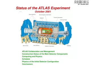
The ATLAS Detector • AToroidal LHC ApparatuS (ATLAS) is a general-purpose particle detector designed to study p-p collisions at the Large Hadron Collider (LHC) at CERN • 1800 physicists, 150 institutes, 35 countries • 42 m length and 11 meters radius • Classical Structure • Inner tracker • Calorimeters • Muon System Alex Barriuso Poy, ICALEPCS 05, Geneva
Control Room Electronics Rooms Cavern Locations of the Detector Control System (DCS) Alex Barriuso Poy, ICALEPCS 05, Geneva
Functions of the DCS • The DCS task is to enable a coherent and safe operation of ATLAS • DCS supervises the hardware in the experiment set-up and the common experimental infrastructure • DCS also interface external systems such us the CERN technical services and the LHC accelerator • The DCS consists of a distributed Back-End running on PCs and of the Front-End instrumentation Back End Front End Alex Barriuso Poy, ICALEPCS 05, Geneva
Organization of the Back-End (i) • The data volume treated by the DCS is large (~200.000 channels) • Long lifetime of the detector (~20 years) • Big collaboration effort (150 institutes, 35 countries) • For the operation many complex systems have to collaborate • The magnitude of ATLAS suggest a hierarchical control structure • Reduce Complexity - Reduce number of distinct elements • Software elements use the Joint COntrol Project (JCOP) framework as much as possible • To group these distinct elements into a small number of modules and to create a control hierarchy. The Finite State Machine (FSM) tool Alex Barriuso Poy, ICALEPCS 05, Geneva
Organization of the Back-End (ii) Partition into modules, and the creation of the hierarchy, involves a division of information into: • Visible Design Rules: To be widely shared throughout the ATLAS community. Must be flexible and not present a constraint on the evolution of the ATLAS DCS • Architecture: Specifies constituent parts and their functions • Interfaces: defines how modules interacts with each other and externally with the person in charge of the operation • Standards: ATLAS guidelines for the implementation of the control hierarchy • Hidden Design Parameters: Encapsulation of specific information of a certain module. Do not need to be communicated beyond the boundaries of the module Alex Barriuso Poy, ICALEPCS 05, Geneva
Experiment LHC Calorimeter Tracker Muon Messages and Commands Sub-det 1 Sub-det 2 Sub-det n Temp Temp GAS Cooling HV HV LV HV LV The FSM Approach • The FSM is the main tool for the implementation of the full control hierarchy in ATLAS • It forms part of the JCOP framework and is based on the commercial SCADA package PVSS-II and SMI++ (State Manager Interface) • The FSM is used to model devices and sub-system behaviour, to automate operations and to attempt recovery from error conditions Alex Barriuso Poy, ICALEPCS 05, Geneva
Experiment LHC Calorimeter Tracker Muon Messages and Commands Sub-det 1 Sub-det 2 Sub-det n Temp Temp HV HV GAS Cooling HV LV LV The FSM Usage • The FSM units (SMI++ objects) can represent devices entities, like a pump, or logical groups of devices like a sub-detector • In that way, detector is broken down into simple FSM units that are hierarchically controlled by other FSMs • The coordination of the different partitions will be performed through commands and messages Alex Barriuso Poy, ICALEPCS 05, Geneva
Visible design rules: ATLAS CIC Pixel SCT TRT LAr Tile MDT TGC CSC RPC Global Control Station Sub-detector Control Station EMB-A EMB-B EMEC-A EMEC-C HEC FCAL DAQ DAQ Partition DDC HV-PS HV THERMO ROD FEC Local Control Station Q1 Q2 Q3 Q4 Geographic partition HV sector 1 HV sector 2 HV sector n Device Units a) Architecture • Specifies constituent parts and their functions • The Back-End has 3 functional layers (~100 PCs) Alex Barriuso Poy, ICALEPCS 05, Geneva
Visible design rules: ATLAS CIC Pixel SCT TRT LAr Tile MDT TGC CSC RPC Global Control Station EMB-A EMB-B EMEC-A EMEC-C HEC FCAL HV-PS HV THERMO ROD FEC Q1 Q2 Q3 Q4 HV sector 1 HV sector 2 HV sector n a) Architecture • Global Control Station (GCS) : • In charge of the overall operation of the detector • High level monitoring and control Alex Barriuso Poy, ICALEPCS 05, Geneva
Visible design rules: ATLAS CIC Pixel SCT TRT LAr Tile MDT TGC CSC RPC Sub-detector Control Station EMB-A EMB-B EMEC-A EMEC-C HEC FCAL DAQ DAQ Partition DDC HV-PS HV THERMO ROD FEC Q1 Q2 Q3 Q4 HV sector 1 HV sector 2 HV sector n a) Architecture • Sub-detector Control Station (SCS): • Allows full, local operation of the sub-detector • At this level connection with Data AcQuisition (DAQ) takes place Alex Barriuso Poy, ICALEPCS 05, Geneva
Visible design rules: ATLAS CIC Pixel SCT TRT LAr Tile MDT TGC CSC RPC EMB-A EMB-B EMEC-A EMEC-C HEC FCAL HV-PS HV THERMO ROD FEC Local Control Station Q1 Q2 Q3 Q4 Geographic partition HV sector 1 HV sector 2 HV sector n Device Units a) Architecture • Local Control Station (LCS): • Low level monitoring and control of instrumentation and services • Data processing and command execution Alex Barriuso Poy, ICALEPCS 05, Geneva
Visible design rules: ATLAS CIC Pixel SCT TRT LAr Tile MDT TGC CSC RPC EMB-A EMB-B EMEC-A EMEC-C HEC FCAL HV-PS HV THERMO ROD FEC Q1 Q2 Q3 Q4 HV sector 1 HV sector 2 HV sector n b) Interfaces • Interface DAQ-DCS • In a certain level the DCS organization is a mirror of the DAQ • Synchronization by means of data, message and command exchange using the DAQ-DCS Communication (DDC) package DAQ DAQ Partition DDC Alex Barriuso Poy, ICALEPCS 05, Geneva
Visible design rules: b) Interfaces • FSM Internal Interface • SMI++ objects can run in a variety of platforms all communications being handled transparently by the underlying package DIM (Distributed Information Management) • Human Interface • It allows to navigate through different levels of the hierarchy • Geographical and System View Alex Barriuso Poy, ICALEPCS 05, Geneva
Visible design rules: ATLAS CIC Pixel SCT TRT LAr Tile MDT TGC CSC RPC B+ EB+ EB- B- Cooling HV LV Cooling HV LV CIC CIC T1 T2 Press c) Standards Messages via a double Information Path – STATE & STATUS • STATEdefines the operational mode of the system (ON, OFF, etc) • STATUS defines how well the system is working (OK, WARNING, ALARM, FATAL) • Two parallel information paths. E.g. HV system is in RAMPING_UP state (which takes several minutes) and an error triggers. The error is propagated through the STATUS while keeping the same STATE COMMANDS STATE STATUS Alex Barriuso Poy, ICALEPCS 05, Geneva
A Prototype User Interface for the GCS Alex Barriuso Poy, ICALEPCS 05, Geneva
ATLAS Global Control Station CIC Pixel SCT TRT LAr Tile MDT TGC CSC RPC Sub-detector Control Station EMB-A EMB-B EMEC-A EMEC-C HEC FCAL TTC Partition HV-PS HV THERMO ROD FEC Local Control Station Q1 Q2 Q3 Q4 Geographic partition Device Units HV sector 1 HV sector 2 HV sector n A Prototype User Interface for the GCS Alex Barriuso Poy, ICALEPCS 05, Geneva
Encapsulated information Example of LCSHV System for the Liquid Argon Calorimeter • Composed by 5000 HV channels Alex Barriuso Poy, ICALEPCS 05, Geneva
Boundaries - Device Units Encapsulated information Example of LCSHV System for the Liquid Argon Calorimeter • Composed by 5000 HV channels • Granularity: • Too fine increases connections FSM-PVSS II. Not needed • Too coarse accumulate too much information • Smallest entities where commands are sent from levels above • HV sector is a physical part of the detector. Behaviour well known • It continues to be applicable in case the Back-End or Front-End evolves Alex Barriuso Poy, ICALEPCS 05, Geneva
Geographic partition Boundaries - Device Units Encapsulated information Example of LCSHV System for the Liquid Argon Calorimeter • Geographic partition • The target is to divide geographically LAr in a common way for all the systems (HV, LV, etc) that form a certain region of the calorimeter • Thus, from levels above 2 views are possible: “System View” and “Geographical View” Alex Barriuso Poy, ICALEPCS 05, Geneva
Local Control Station DAQ partitions EMBA EMBC EMECA EMECC HEC FCAL Geographic partition Boundaries - Device Units Encapsulated information Example of LCSHV System for the Liquid Argon Calorimeter • DAQ partition • DAQ is the Master and DCS the Slave • LCSs must respect the DAQ partition in order to build the SCS Alex Barriuso Poy, ICALEPCS 05, Geneva
Messages and Commands Prototype Implementation • The performance of the proposed standards and organization has been studied • The largest setup contained more than 10.000 modules which is a factor three more than expected for a sub-detector • Performance fulfill requirements SCS LCS 2 LCS 3 LCS 1 LCS 12 Sys 1 Sys 2 Sys 3 Sub-det 1 Sub-Sys 2 Sub-Sys 3 Sub-Sys 1 HW HW HW HW HW Alex Barriuso Poy, ICALEPCS 05, Geneva
Conclusions • Due to the complexity and size of the detector, a hierarchical organization has been chosen • A set of rules for the design of the hierarchy has been defined • These rules provide the flexibility to take into account the experience that will be gained during the long lifetime operation of the detector, as well as to allow for future evolution of the control system • The granularity of the hierarchy, its architecture and internal interfaces have been investigated with the aim to study the overall system performance Alex Barriuso Poy, ICALEPCS 05, Geneva
Hierarchical Control for the ATLAS Experiment A. Barriuso, H. Burckhart, J. Cook, F. Varela. CERN, Geneva. V. Filimonov , V. Khomutnikov, Y. Ryabov. PNPI, St. Petersburg. L. Carminati. INFN, Milan.
10.-State: ON Status: from OK to ALARM 9.- The state is propagated 8.- State: ON Status: from OK to ALARM 6.- State: ON Status: from OK to ALARM 7.- The state is propagated 11.- Turn Off 5.- The state is propagated 14.- State from ON to OFF Status: ALARM 4.-State: ON Status: from OK to ALARM 3.- Status is propagated 12.- Set outputs 2.-State: ON Status: from OK to ALARM 13.- State from ON to OFF Status: Alram 1.- Temp too high ID Pixel SCT TRT EC1 BL L1 L2 EC2 Pow Env Cool Pow Env Cool Dev1 Dev2 … Dev1 Dev2 … Dev1 Dev2 … Alex Barriuso Poy, ICALEPCS 05, Geneva
STATE STATUS CU Child CU Child CU Child CU Child DU DU DU CU Top CU Top CU Top &Obj Status &Obj Status Proxy Proxy Proxy Obj Status Control Unit &Obj Status &Obj Status Obj Status Obj Status Control Unit Control Unit Hardware Devices Alex Barriuso Poy, ICALEPCS 05, Geneva
EMBA and EMBC geographic division • Accordion • 4 quadrants 4 CU • 4 quadrants x 7 sectors x 8 sectors 224 DU • Presampler • 4 quadrants x 4 sectors x 8 sectors 128 DU • 4 quadrants 4 CU • Outer wheel • 4 quadrants x 7 sectors x 8 sectors 224 DU • Inner wheel • 4 quadrants x 2 sectors x 16 sectors 128 DU • Presampler • 4 quadrants x 2 sectors x 8 sectors 64 DU Alex Barriuso Poy, ICALEPCS 05, Geneva
HECA/HECC FSM structure proposal • 4 quadrants 4 CU • 4 quadrants x 8 sectors x 4 layers 128 DU • 3 layers 3 CU • 16 DU in the first layer • 8 DU in the second layer • 4 DU in the third layer Alex Barriuso Poy, ICALEPCS 05, Geneva
DU/CU numbers for HV system HV control system EMBA/C EMBPSA/C EMECA/C EMECPSA/C HEC FCAL 3 layers 4 quadrant 4 quadrant 4 quadrant 4 quadrant 4 quadrant HV sectors HV sectors HV sectors HV sectors HV sectors HV sectors Iseg Ch. Iseg Ch. Iseg Ch. Iseg Ch. Iseg Ch. Iseg Ch. Alex Barriuso Poy, ICALEPCS 05, Geneva
FSM for the Common Infrastructure Control (CIC) Alex Barriuso Poy, ICALEPCS 05, Geneva