Download
1 / 30
320 likes | 541 Vues
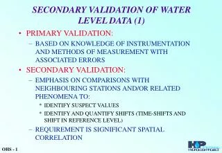
Acquisition and Interpretation of Water-Level Data. Travis von Dessonneck. Importance of Water-Level Data. The acquisition and interpretation of ground-water data are essential for environmental site assesment Can be used to determine hydraulic head in formations Used to make 3D flow patterns.

E N D
Acquisition and Interpretation of Water-Level Data Travis von Dessonneck
Importance of Water-Level Data • The acquisition and interpretation of ground-water data are essential for environmental site assesment • Can be used to determine hydraulic head in formations • Used to make 3D flow patterns
Water level and Hydraulic-head relationships • Hydraulic head varies spatially and temporally • Piezometer • Monitoring device for measuring water levels • Hollow vertical pipe with a screen • Elevation head • The elevation of the bottom of the well/piezometer
Water level and Hydraulic-head relationships • Pressure head • The height of the water above the bottom of the well • Total hydraulic head • Elevation head + Pressure head
Hydraulic Media and aquifer systems • Aquifer is not “a water-bearinglayer of geologic material, which will yield water in a usable quantity to a well or spring” in this instance • Aquifer is where water lies with respect to the top of a geologic unit
Design features for water-level monitoring systems • Takes into account water-level monitoring and sampling • 2 phases • Site data collection • Monitoring for changes and proper placement of wells • Can also be used to determine if monitoring system is not set up correctly • Site geology must be known • Heterogeneous sites require more monitoring than homogeneous sites
Piezometers or wells • Piezometers are generally not used to gather water samples • Small diameter pipe • Can accommodate pressure transducers • Wells are designed for sampling • Larger diameter
Approach to system designs • What to consider • Boring and well logs • Surficial geology • Topographic maps • Drainage features • Cultural features (well fields, irrigation, pipes) • Rainfall • Recharge
Approach to system designs • Review the data to get • Depth and characteristics of high and low K areas • Depth to water, intermittent or perched zones • Flow direction • Vertical hydraulic gradients • Possible causes and frequency of fluctuation • Existing wells that may be incorporated
Number and placement of wells • Dependant on size and complexity of site • Minimum to establish direction and rate of flow • Larger sites usually have a grid of six to nine wells to get direction • Take into account screen depth and length
Water-level measurement precision and intervals • Need to accurately located wells vertically and horizontally • Survey/GPS • Accuracy to 0.1 and 0.01 ft • Need to know what you are looking for • Seasonal changes • Diurnal changes
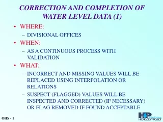
Reporting of data • Monitoring installations • Geologic sequence • Well construction features • Depth and elevation of well casing • Water-level data • Date and time of measurement • Method used • Other conditions that might affect the well level
Manual measurements in nonflowing wells • Wetted chalked tape method • Weight attached to bottom of tape • Coat bottom 2-3ft of tape with carpenter’s chalk • Accurate to 0.01ft (USGS 1980) • Disadvantages • Stretching of the tape • Need to know approximate depth to water
Manual measurements in nonflowing wells • Air-line submergence method • Insert a small diameter tube below the water surface • Pump the water out the bottom by hand or electric pump • Ending psi * 2.31 gives feet • Subtract the calculated distance from length of tube
Manual measurements in nonflowing wells • Electrical methods • Whistler • Open circuit is completed when it comes in contact with the water and beeps at you • Wires are at the end of a measuring tape • Read the tape to determine depth
Manual measurements in nonflowing wells • Pressure transducer methods • Measures the pressure in the well at the sensor • Open to the atmosphere by a small capillary tube • Usually have a sealed data logger • Sensor is lowered a known distance into the water when installed
Manual measurements in nonflowing wells • Float method • A float is attached to the end of a steel tape • Read the depth off of the steel tape
Manual measurements in nonflowing wells • Sonic or audible methods • The classic “drop the pebble in the well approach” only with a tape attached to the pebble • Drop a battery powered probe down the beeps when it is in the water (whistler)
Manual measurements in nonflowing wells • Ultrasonic/radar/laser methods • A sonar type device • Calculates the reflection time • Can get depth to water and total depth of the well
Manual measurements in flowing wells • Manometers and pressure gauges • Well is sealed and a pressure gauge is installed in the top • Mercury can be accurate to 0.005ft • Pressure gauges can be accurate to 0.2 ft
Methods of Continuous measurement • Mechanical: float recorder systems • A float attached to a seismometer type drum • Electromechanical: Iterative Conductance Probes (dippers) • Probe is lowered to the water surface by a stepping motor • Sensor like on a whistler tells the motor to stop • Motor reverses and repeats at set intervals • Data loggers
Analysis, Interpretation, and Presentation of Water-level data • Water-level can be effected by recharge and discharge conditions • Water flows down during recharge and up during discharge
Approach to Interpreting Water-level data • Conduct a thorough site analysis • Review monitoring wells features • Establish groundwater flow direction and magnitude • Monitor for several days to see long term fluctuations
Transient Effects • Water level can change due to many things • Seasonal precipitation • Irrigation • Well pumping • River stage • Tidal fluctuations • These can reverse flow direction
Contouring water level elevation data • Made like a topo map, only of the water table and not the surface elevation • May require cross sections in areas with high vertical flow