ONE LIBERTY CENTER
ONE LIBERTY CENTER. MICHAEL ROMESBURG STRUCTURAL OPTION APRIL 15, 2003 SENIOR THESIS THE PENNSYLVANIA STATE UNIVERSITY DEPARTMENT OF ARCHITECTURAL ENGINEERING. Presentation Outline. DESIGN TEAM PROJECT OVERVIEW EXISTING CONDITIONS PROBLEM STATEMENT PROPOSED SOLUTION

ONE LIBERTY CENTER
E N D
Presentation Transcript
ONE LIBERTY CENTER MICHAEL ROMESBURG STRUCTURAL OPTION APRIL 15, 2003 SENIOR THESIS THE PENNSYLVANIA STATE UNIVERSITY DEPARTMENT OF ARCHITECTURAL ENGINEERING
Presentation Outline • DESIGN TEAM • PROJECT OVERVIEW • EXISTING CONDITIONS • PROBLEM STATEMENT • PROPOSED SOLUTION • FIRE PROTECTION BREADTH • CONSTRUCTION BREADTH • RECCOMENDATIONS
DESIGN TEAM: ARCHITECT CIVIL ENGINEER GENERAL CONTRACTOR TOLK, Inc. MECHANICAL ELECTRICAL AND PLUMBING STRUCTURAL ENGINEER
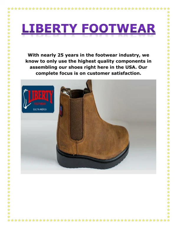
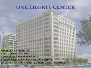
Background Information • Office building; 13 typical floors, 5 floors of sub-grade parking • 300,000 sq. ft. of rentable office space • Fully developed urban site • Precast and glass facade
Background Information • Estimated total cost of $42.5 million • Design documents completed August 2003 • Project bid was 9-16-02 • Site clearing and demolition started in October • Proposed finish is December 2004
Original Structural Design • Floor system: Two-way flat slab with drops • Lateral system: Concrete frames • Foundation: Spread footings • Floor to floor height: 11’-6” • Total plenum depth: 36” leaving 8’-6” floor to ceiling heights
Possible Problems • Columns in office space • Long schedule for concrete due to: forming, reinforcing, pouring, stripping, shoring, and reshoring
Solutions • Use Fy = 50 ksi steel above grade in office spaces: • May speed up the schedule • Can get rid of columns in the office space while keeping the building the same size • Different systems tried: • Steel beams and girders with composite deck • Steel joists and girders with composite deck • Composite beams and girders with composite deck
Design Criteria • Basis: • International Building Code (IBC 2000) • American Society of Civil Engineers (ASCE 7-98) • Load and Resistance Factor Design (LRFD Second Edition) • Building Criteria: • Floor to floor height remains 11’-6” • Minimal impact on architecture and interiors • Cost • Schedule
Selection of New System • Non-composite steel members deflect too much over the new 50’ span; resulting in very deep members and enlarge plenum • Joists are very difficult to fireproof; resulting in added labor costs • Composite steel system preliminary sizes allow the plenum to remain the same size Try a new floor design using composite steel.
Composite Steel Design • Slab (Information from United Steel Deck Manual): • Light weight concrete • 5” total thickness • 16 gauge, 24” wide, 1.5” Lok-Floor • Reasons selected: • Used on 2 or 3 spans no shoring is required under 10’ • Meets fire rating requirements of 2 hours without added fire protection
Composite Steel Design • Typical beam: • Spaced at 10’ on center • Spans 30’ • LL = 100 psf (including partition loads) • DL = 50 psf • Resulting beam: • W16x26 (16) camber = 1.0” • Deflection due to wet concrete = 1.0” • L/360 limit is 1.0” • Live load deflection after composite action is less than 0.9” • No Shoring Required
Composite Steel Design • Typical girder: • Spaced at 30’ on center • Spans 50’ • LL = 100 psf (including partition loads) • DL = 50 psf • Resulting beam: • W30x116 (104) camber = 1.25” • Deflection due to wet concrete = 1.48” • L/360 limit is 1.67” • Live load deflection after composite action is less than 1.60” • No Shoring Required
Composite Steel Design • Typical column: • Factored loads • Roof Load = 105psf • Reduced Live Load = 65psf except 85psf top floor • Total Load = 1310k at bottom floor • Typical sizes: W14x120 and W14x132
Composite Steel Design • Typical change in spread footing: • Flat slab concrete design: • 8’-0” square by 46” deep • Composite steel design: • 6’-6” square by 36” deep • Savings of 5 to 15 yards of concrete for every footing
Composite Steel Design Typical floor cross section: Structural and duct system fit tightly into the 36” plenum space with an inch to spare
Lateral System • Without concrete frames a new problem arises: • What will the new lateral system be? • Shear walls: Height of the building creates moments that are difficult for the shear walls to resist • Braced frames: Limited number of locations, but can work with relatively large members
Lateral System and Center of Rigidity All frames are cross braced with 2L8x8x1-1/8 and 2L4x4x3/4 horizontally and vertically respectively
Fire Protection Breadth • Changing to steel requires new fire protection measures for the structure • Spray on fire proofing is quick and easy • Basis: • Underwriters Laboratories Inc. (UL) Directory of Fire Resistance Vol. 1 ANSI/UL 263
Fire Protection Breadth • Building Criteria: • 2 hr. rated floor construction (including beams) • 3 hr. rated column coverage • Solution: • Slab: USD manual and Design # D916 in UL • 16 gauge, 24” wide, 1.5” Lok-Floor • 3.5” LW concrete above flutes, no additional fireproofing • Beams and Girders: Design # D916 in UL • 0.75” Spray-on fireproofing • 0.33” Fireproofing on lower flange edge to allow slightly more room in plenum
Fire Protection Breadth • Solution: • Columns: Design # Y724 in UL • 1.75” Spray-on fireproofing • Acceptable products for both columns and beams by: • WR Grace & Co. – Conn. • Construction Products Div. • Grace Korea Inc.
Construction Breadth • Assumptions in estimating costs and scheduling • R.S. Means 2003 • One crew designated by Means used for each item unless noted otherwise • All material, labor, and equipment costs are included • Broken into steel members, slab, deck, wire fabric, steel studs, and fire proofing
Construction Breadth • Cost analysis (structure above grade): • Initial concrete cost: $5,989,000 • $18.34 / sq.ft. • Initial steel cost: $4,559,000 • $13.96 / sq.ft. • Total Savings: $1,430,000 • $4.38 / sq.ft.
Construction BreadthNew Schedule • Steel members erected 37 pieces per day leaving a 20 day float • Wire fabric is the critical item taking 96 days
Construction Breadth New Schedule • Shear studs are erected in two phases to stay ahead of concrete and behind steel erection • Total duration is 106 days and is 34 work days less than the original concrete schedule
Conclusion • Steel is erected faster (one months extra rent may be charged) • Steel is cheaper by 24% • Composite steel system eliminates columns in office spaces • Redesign is succesful
Recommendations • Based on cost and scheduling choose composite steel and composite deck system in above grade office spaces • Investigate use of similar system in below grade parking deck, savings may not be as great due to lower loads and less premium space
Thank You SK&A AE Faculty and Staff AE Class of 2003