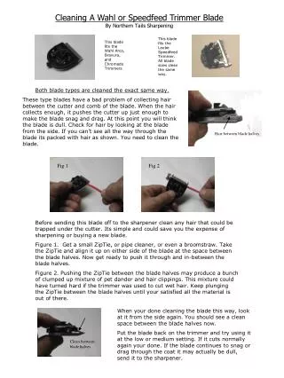
Part I: Blade Design Methods and Issues
Part I: Blade Design Methods and Issues. James L. Tangler Senior Scientist. National Renewable Energy Laboratory National Wind Technology Center. Steady-State Aerodynamics Codes for HAWTs Selig, Tangler, and Giguère August 2, 1999 ï§ NREL NWTC, Golden, CO. Outline.


Part I: Blade Design Methods and Issues
E N D
Presentation Transcript
Part I: Blade Design Methods and Issues James L. Tangler Senior Scientist National Renewable Energy Laboratory National Wind Technology Center Steady-State Aerodynamics Codes for HAWTs Selig, Tangler, and Giguère August 2, 1999 NREL NWTC, Golden, CO
Outline • Survey of Steady-Aerodynamics Codes • Blade Design Trade-Offs and Issues • Wind Turbine Airfoils • Noise Sources and Tip Shapes • Stall-Delay Models
Survey of Steady-Aerodynamics Codes • Historical Development of BEMT Performance and Design Methods in the US • Summary Year Codes Developers 1974 PROP Wilson and Walker 1981 WIND Snyder 1983 Revised PROP Hibbs and Radkey PROPSH Tangler WIND-II Snyder and Staples 1984 PROPFILE Fairbank and Rogers
Year Code Developer 1986 NUPROP Hibbs 1987 PROPPC Kocurek 1993 PROP93 McCarty 1994 PROPID Selig 1995 WIND-III Huang and Miller PROPGA Selig and Coverstone-Carroll 1996 WT_PERF Buhl 1998 PROP98 Combs 2000 New PROPGA Giguère
Some details of each code 1974 PROP – Fortran 77 1981 WIND – Based on PROP code – Accounts for spoilers, ailerons, and other airfoil modifications 1983 Revised PROP – Windmill brake state – Wind shear effects – Flat-plate post-stall airfoil characteristics
1983 continue PROPSH – Rotor shaft tilt option – Dimensional outputs WIND-II – Empirical axial induction models – 2D airfoil data – Energy computation 1984 PROPFILE – PC version of PROPSH
1986 NUPROP – Dynamic stall – Wind shear – Tower shadow – Yaw error – Large scale turbulence 1987 PROPPC – PC version of PROP 1993 PROP93 – PROP with graphical outputs – Programmed in C
1994 PROPID – Inverse design method – Airfoil data interpolation – Improved tip-loss model 1995 WIND-III – PC version of WIND-II – Accounts for various aero breaking schemes PROPGA – Genetic-algorithm based optimization method – Optimize for max. energy – Uses PROPID
1996 WT_PERF – Improved tip-loss model – Drag term in calculating inplane induced velocities – Fortran 90 1998 PROP98 – Enhanced graphics – Windows Interface 2000 New PROPGA – Structural and cost considerations – Airfoil selection – Advanced GA operators – Multi objectives
Types of Steady-State BEMT Performance and Design Methods Analysis Inverse Design Optimization PROP PROPID PROPGA WIND Revised PROP PROPSH WIND-II PROPFILE NUPROP PROPPC PROP93 WIND-III WT_PERF PROP98
Glauert Correction for the Viscous Interaction • less induced velocity • greater angle of attack • more thrust and power
Prediction Sources of Error • Airfoil data • Correct Reynolds number • Post-stall characteristics • Tip-loss model • Generator slip RPM change
How Is Lift and Drag Used? • Only lift used to calculate the axial induction factor a • Both lift and drag used to calculate the swirl a’
Designing for Steady-State Performance vs Performance in Stochastic Wind Environment • Turbulence • Wind shear • Dynamic stall • Yaw error • Elastic twist • Blade roughness
Blade Design Trade-offs and Issues • Aerodynamics vs Stuctures vs Dynamics vs Cost • The aerodynamicists desire thin airfoils for low drag and minimum roughness sensitivity • The structural designers desire thick airfoils for stiffness and light weight • The dynamicists desires depend on the turbine configuration but often prefer airfoils with a soft stall, which typically have a low to moderate Clmax • The accountant wants low blade solidity from high Clmax airfoils, which typically leads to lower blade weight and cost
Low-Lift vs High-Lift Airfoils • Low-lift implies larger blade solidity, and thus larger extreme loads • Extreme loads particularly important for large wind turbines • Low-lift airfoils have typically a soft stall, which is dynamically beneficial, and reduce power spikes • High-lift implies smaller chord lengths, and thus lower operational Reynolds numbers and possible manufacturing difficulties • Reynolds number effects are particularly important for small wind turbines
Optimum Rotor Solidity • Low rotor solidity often leads to low blade weight and cost • For a given peak power, the optimum rotor solidity depends on: • Rotor diameter (large diameter leads to low solidity) • Airfoils (e.g., high clmax leads to low solidity) • Rotor rpm (e.g., high rpm leads to low solidity) • Blade material (e.g, carbon leads to low solidity) • For large wind turbines, the rotor or blade solidity is limited by transportation constraints
Swept Area (2.2 - 3.0 m2/kW) • Generator rating • Site dependent • Blade Flap Stiffness ( t2) • Airfoils • Flutter • Tower clearance
Rotor Design Guidelines • Tip speed: < 200 ft/sec (61 m/sec ) • Swept area/power: wind site dependent • Airfoils: need for higher-lift increases with turbine size, weight. & cost ~ R2.8 • Blade stiffness: airfoil thickness ~ t2 • Blade shape: tapered/twisted vs constant chord • Optimize cp for a blade tip pitch of 0 to 4 degrees with taper and twist
Wind Turbine Airfoils • Design Perspective • The environment in which wind turbines operate and their mode of operation not the same as for aircraft • Roughness effects resulting from airborne particles are important for wind turbines • Larger airfoil thicknesses needed for wind turbines • Different environments and modes of operation imply different design requirements • The airfoils designed for aircraft not optimum for wind turbines
Design Philosophy • Design specially-tailored airfoils for wind turbines • Design airfoil families with decreasing thickness from root to tip to accommodate both structural and aerodynamic needs • Design different families for different wind turbine size and rotor rigidity
Main Airfoil Design Parameters • Thickness, t/c • Lift range for low drag and Clmax • Reynolds number • Amount of laminar flow
Design Criteria for Wind Turbine Airfoils • Moderate to high thickness ratio t/c • Rigid rotor: 16%–26% t/c • Flexible rotor: 11%–21% t/c • Small wind turbines: 10%-16% t/c • High lift-to-drag ratio • Minimal roughness sensitivity • Weak laminar separation bubbles
NREL Advanced Airfoil Families Note: Shaded airfoils have been wind tunnel tested.
Potential Energy Improvements • NREL airfoils vs airfoils designed for aircraft (NACA)
Other Wind Turbine Airfoils • University of Illinois • SG6040/41/42/43 and SG6050/51 airfoil families for small wind turbines (1-10 kW) • Numerous low Reynolds number airfoils applicable to small wind turbines • Delft (Netherlands) • FFA (Sweden) • Risø (Denmark)
Airfoil Selection • Appropriate design Reynolds number • Airfoil thickness according to the amount of centrifugal stiffening and desired blade rigidity • Roughness insensitivity most important for stall regulated wind turbines • Low drag not as important for small wind turbines because of passive over speed control and smaller relative influence of drag on performance • High-lift root airfoil to minimize inboard solidity and enhanced starting torque
Noise Sources and Tip Shapes • Noise Sources • Tip-Vortex / Trailing-Edge Interaction • Blade/Vortex Interaction • Laminar Separation Bubble Noise
Tip Shapes • Sword Shape Swept Tip
Thick and Thin Trailing Edge Noise Measurements • Thick Tip trailing Edge Thin Tip Trailing Edge
Stall-Delay and Post-Stall Models • Stall-Delay Models • Viterna • Corrigan & Schillings • UIUC model
Corrigan & Schillings Stall-Delay Model • Simplified equations
Examples • CER1 Constant chord/non-twist blade
UIUC Stall-Delay Model • Easier to tailor to CER test data than Corrigan & Schillings model • More rigorous analytical approach • Results in greater blade root lift coefficient enhancement than Corrigan & Schillings model
Conclusions on Post-Stall Models • The Corrigan & Schillings stall delay model quantifies stall delay in terms of blade geometry • Greater blade solidity and airfoil camber resulted in greater stall delay • Tapered blade planform provided the same % peak power increase as constant-chord blade with lower blade loads • Predicted CER peak power with stall delay was 20% higher • Peak power increases of 10% to 15% are more realistic for lower solidity commercial machines