Coordinate
Coordinate. Systems. Required readings: Coordinate systems:19-1 to 19-6. State plane coordinate systems: 20-1 to 20-5, 20-7, 20-10, and 20-12. Required figures: Coordinate systems: 19-1, 19-2, 19-6, 19-7 and 19-8. State plane coordinate systems: 20-1 to 20-3, 20-10.

Coordinate
E N D
Presentation Transcript
Coordinate Systems
Required readings: • Coordinate systems:19-1 to 19-6. • State plane coordinate systems: 20-1 to 20-5, 20-7, 20-10, and 20-12. • Required figures: • Coordinate systems: 19-1, 19-2, 19-6, 19-7 and 19-8. • State plane coordinate systems: 20-1 to 20-3, 20-10. • Recommended, not required, readings: 19-7 to 19-11, 20-11, and 20-13.
Coordinate Systems • Geoid and Ellipsoid, what for?
Ellipsoid Parameters • Ellipsoid parameters (equations not required): • semi-major axes (a), semi-minor axes (b) • e = = first eccentricity • N = normal length = • Great circles and meridians • Two main ellipsoids in North America: • Clarke ellipsoid of 1866, on which NAD27 is based • Geodetic Reference System of 1980 (GRS80): on which NAD83 is based. • For lines up to 50 km, a sphere of equal volume can be used
Geodetic Coordinate System • System components, coordinates
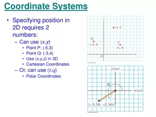
Geodetic System Coordinates • Definitions : • Geodetic latitude (f): the angle in the meridian plane of the point between the equator and the normal to the ellipsoid through that point. • Geodetic longitude (l): the angle along the equator between the Greenwich and the point meridians • Height above the ellipsoid (h)
Universal Space Rectangular System • System definition, X, Y, Z • Advantage and disadvantage • X, Y, Z from geodetic coordinates X = (N+h) cosf cosl Y = (N+h) cosf sinl Z = ( N(1-e2) +h) sinf Z Y X
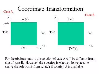
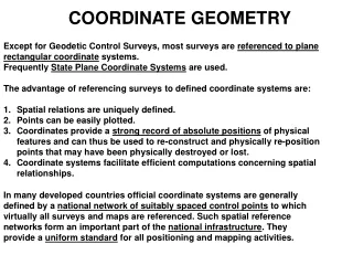
State Plane Coordinate Systems • Plane rectangular systems, why use them? • How to construct them: Project the earth’s surface onto a developable surface. • Two major projections: Lambert Conformal Conic, and Transverse Mercator.
Secants, Scales, and Distortions • Scale is exact along the secants, smaller than true in between. • Distortions are larger away from the secants
Choosing a Projection • States extending East-west: Lambert Conical • States extending North-South: Mercator Cylindrical. • A single surface will provide a single zone. Maximum zone width is 158 miles to limit distortions to 1:10,000. States longer than 158 mi, use more than one zone (projection).
Standard Parallels & Central Meridians • Standard Parallels: the secants, no distortion along them. At 1/6 of zone width from zone edges • Central Meridians: a meridian at the middle of the zone, defines the direction of the Y axis. • The Y axis points to the grid north, which is the geodetic north only at the central meridian • To compute the grid azimuth ( from grid north) from geodetic azimuth ( from geodetic north): grid azimuth = geodetic azimuth - q
Geodetic and SPCS • Control points in SPCS are initially computed from Geodetic coordinates (direct problem). If NAD27 is used the result is SPCS27. If NAD83 is used, the result is SPCS83. • Define: q, R, Rb, C, and how to get them.
Direct and Inverse Problems • Direct (Forward): • given: f, l get X, Y? • Solution: X = R sin q + C • Y = Rb - R cos q • Whenever q is used, it is -ve west (left) of the central meridian. • q = geodetic azimuth - grid azimuth • Indirect (Inverse): Solve the above mentioned equations to compute R, and q. Use tables to compute f, l . • In both cases, use a computer program whenever is available. Wolfpack can do it, see next slide.
q = geodetic azimuth - grid azimuth Grid N Grid N B Geodetic N Geodetic N Grid Az A Geodetic Az Geodetic Az Central Meridian of the zone Central Meridian of the zone Grid Az q q POSITIVE at point A East of the CM : NEGATIVE at point A West of the CM
Forward Computations: given (f, l) get (X, Y). • Inverse Computations: given (X, Y) get (f, l)
Surveys Extending from one Zone to Another • There is always an overlap area between the zones. • When in the transition zone, compute the geodetic coordinates of two points from their X, Y in first zone (direct problem). • Compute X, Y of the same points in the second zone system from their geodetic coordinates (inverse problem) • Compute the azimuth of the line, use the azimuth and new coordinates to proceed.
PI (V) C T PC
Two vertical curves can be set-out at the same time from either BVC 1 or BVC 2. The direction of each of the Centerlines curves is shown to the left. Assume that the BM for elevation is BVC and IS NOT 20 BVC 1 20 BVC 2 Last tree Yellow-to post