Download

1 / 115
1.19k likes | 1.52k Vues
Explore Raspberry Pi board configurations and architectures, learn about interfaces like 1-wire, serial, and USB. Discover the evolution from Model 1 to Model 2, all powered by ARM technology.

E N D
ARM case-study: the raspberry pi RazvanBogdanMicroprocessor Systems
Content • Raspberry Pi Board Configurations • Architecture Overview • Interfacing the Pi • 1-wire interface • Serial Interface • USB Interface
Introduction • Created by Eben Upton, Rob Mullins, Jack Lang and Alan Mycroft at University of Cambridge • They, in conjunction with Pete Lomas and David Braben, formed the Raspberry Pi Foundation • Was created to provide inexpensive programming machines • Raspberry Pi is a small, cheap ARM-based PC for education • Runs Debian GNU/Linux from an SD card • Now the Raspberry Pi is being considered as a popular platform for embedded systems • The Raspberry Pi is an open hardware platform, which means the schematics for the board is publicly published • The Raspberry Pi comes in different models and configurations
Introduction. Raspberry Pi Roadmap • February 2016 – Raspberry Pi 3
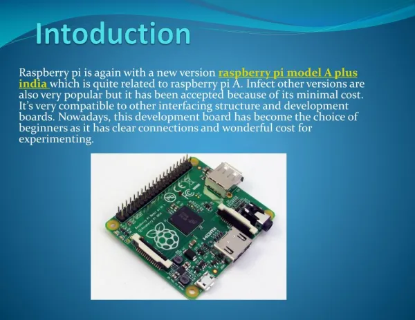
Raspberry Pi Board Configurations Raspberry Pi 1 • Initially it was decided to have two main models, • Model A: A low cost model (around $25) with less capabilities • Model B: A higher cost model (around $35) • Model B was first released in Feb 2012, while Model A was first released in Feb 2013 • Model A did not get much attention • The Model B went through two revisions, with minor changes • Model B rev 1 • Model B rev 2 (Released in Sept 2012) • Aiming for using the Raspberry Pi in commercial and industrial products, the Raspberry Pi Compute module was announced in April 2014, this is a new form factor (200 Pin SO-DIMM Form factor), and much more signals available for developer than the other form • In July 2014, a new model (Model B+) was released, with few upgrades in the power supply, USB ports, GPIOs and other changes • In Nov. 2014, a new model (Model A+) was released with several upgrades from the original Model A
Raspberry Pi Board Configurations Raspberry Pi 1
Raspberry Pi Board Configurations Raspberry Pi 1
Raspberry Pi Board Configurations Raspberry Pi 1 • SoC: Broadcom BCM2835 media processor system-on-chip featuring: • CPU core: ARM1176JZF-S ARM11 core clocked at 700MHz. The ARM11 core implements the ARMv6 Architecture. • GPU core: a Broadcom VideoCore IV GPU providing OpenGL ES 1.1, OpenGL ES 2.0, hardware-accelerated OpenVG 1.1, Open EGL, OpenMAX and 1080p30 H.264 high-profile decode. • DSP core • 256MiB of (Hynix MobileDDR2 or Samsung Mobile DRAM) SDRAM (or 512MB Mobile DRAM on later boards). The RAM is physically stacked on top of the Broadcom media processor (package-on-package technology).
Raspberry Pi Board Configurations Raspberry Pi 1 • LAN9512 (Model B) providing: • 10/100Mb Ethernet (Auto-MDIX), • 2x USB 2.0 • S1: Micro USB power jack (5v - Power Only) • S2: DSI (Display Serial Interface) interface. 15-pin surface mounted flat flex connector, providing two data lanes, one clock lane, 3.3V and GND. • S3: HDMI connector providing type A HDMI 1.3a out; S4: Composite Video connector: RCA; S5: MIPI CSI (Camera Serial Interface)-2 interface. 15-pin surface mounted flat flex connector. • S6: Audio connector: 3.5mm stereo jack (output only); S8: SD/MMC/SDIO memory card slot (underside); S7: Either 1x USB 2.0 (Model A) 2x USB 2.0 (Model B)
Raspberry Pi Board Configurations Raspberry Pi 1 • P1: 26-pin (2x13) 2.54 mm header expansion, providing • 8 GPIOs (General-purpose input/output) at 3v3 • 2-pin UART serial console, 3v3 TTL (debug); or 2 GPIOs at 3v3 • I²C interface (3v3); or 2 GPIOs at 3v3 • SPI interface (3v3); or 5 GPIOs at 3v3 • 3v3, 5v and GND supply pins • ARM JTAG (Joint Test Action Group) • I²S (Integrated Interchip Sound) interface • TP1 and TP2: Test Points giving access to +5V and GND respectively • 5 Status LEDs: • D5(Green) - SDCard Access (via GPIO16) - labelled as "OK" on Rev1.0 boards and "ACT" on Rev2.0 boards • D6(Red) - 3.3 V Power - labelled as "PWR" on both Rev1.0 and Rev2.0 boards • D7(Green) - Full Duplex (LAN) (Model B) - labelled as "FDX" on both Rev1.0 and Rev2.0 boards • D8(Green) - Link/Activity (LAN) (Model B) - labelled as "LNK" on both Rev1.0 and Rev2.0 boards • D9(Yellow) - 10/100Mbit (LAN) (Model B) - labelled (incorrectly) as "10M" on Rev1.0 boards and "100" on Rev2.0 boards
Raspberry Pi Board Configurations Raspberry Pi 1
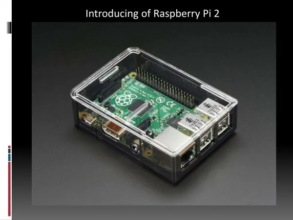
Raspberry Pi Board Configurations Raspberry Pi 2 • Uses a different Broadcom chip (BCM2836) • A big upgrade from the older platforms • Quad core ARM Cortex A7(900 MHz) • 1 GB SDRAM • The new ARM Core supports the ARMv7 Instruction set • This enables it to run Ubuntu and Windows 10 OSs • Fully backward compatible with the older models • Like the (Pi 1) Model B+, it also has: • 4 USB ports • 40 GPIO pins • Full HDMI port • Ethernet port • Combined 3.5mm audio jack and composite video • Camera interface (CSI) • Display interface (DSI) • Micro SD card slot • VideoCore IV 3D graphics core
Raspberry Pi Board Configurations Raspberry Pi 2
Raspberry Pi Board Configurations Raspberry Pi 3 • SoC: Broadcom BCM2837 • CPU: 4× ARM Cortex-A53, 1.2GHz • GPU: Broadcom VideoCore IV • RAM: 1GB LPDDR2 (900 MHz) • Networking: 10/100 Ethernet, 2.4GHz 802.11n wireless • Bluetooth: Bluetooth 4.1 Classic, Bluetooth Low Energy • Storage: microSD • GPIO: 40-pin header, populated • Ports: HDMI, 3.5mm analogue audio-video jack, 4× USB 2.0, Ethernet, Camera Serial Interface (CSI), Display Serial Interface (DSI)
Raspberry Pi Board Configurations Raspberry Pi 3
Raspberry Pi Board Configurations Raspberry Pi 3 http://hackaday.com/2016/02/28/introducing-the-raspberry-pi-3/
Raspberry Pi Board Configurations Raspberry Pi 3 the biggest gains go to multi‐threaded programs
Raspberry Pi Board Configurations Raspberry Pi 3 The Raspberry Pi’s GPIO pins are most commonly used with Python, but this leads to a CPU bottleneck. In this test, a simple RPi.GPIO program toggles a pin as rapidly as possible while a frequency counter measures how quickly it actually switches.
Raspberry Pi Board Configurations Raspberry Pi 3 The classic twitch shooter from industry pioneer id Software, Quake III Arena is heavily tied to the CPU performance of the Pi. The standard ‘timedemo’ was run at 1280×1024, high geometric, maximum texture detail, 32-bit texture quality, and trilinear filtering to obtain these results.
Raspberry Pi Board Configurations Raspberry Pi 3 You can’t get extra performance without a few sacrifices. The Pi 3 draws the most power of the test group, but its extra performance means it spends more time at idle. Those looking for maximum battery life should look at the Model A+ or the Pi Zero as an alternative. Source: https://www.raspberrypi.org/magpi/raspberry-pi-3-specs-benchmarks/
Architecture Overview. System on Chip (SoC) • System on a chip or system on chip (SoC or SOC) • an integrated circuit (IC) that integrates all components of a computer or other electronic system into a single chip. • It may contain digital, analog, mixed-signal, and often radio-frequency functions—all on a single chip substrate. • SoCs are very common in the mobile electronics market because of their low power consumption
System on Chip (SoC) • A typical SoC consists of: • a microcontroller, microprocessor or digital signal processor (DSP) core – multiprocessor SoCs (MPSoC) having more than one processor core • memory blocks including a selection of ROM, RAM, EEPROM and flash memory • timing sources including oscillators and phase-locked loops • peripherals including counter-timers, real-time timers and power-on reset generators • external interfaces, including industry standards such as USB, FireWire, Ethernet, USART, SPI • analog interfaces including ADCs and DACs • voltage regulators and power management circuits • ARM Advanced Microcontroller Bus Architecture (AMBA) Interface (an open-standard, on-chip interconnect specification for the connection and management of functional blocks in system-on-a-chip (SoC) designs)
System on Chip (SoC) • Benefits of SoC • Reduce overall system cost • Increase performance • Lower power consumption • Reduce size
System on Chip (SoC). BCM2835 • The Raspberry Pi 1 main chip is the Broadcom BCM2835 System on a Chip (SoC); it contains a single ARM core CPU (ARM11, ARM1176) running at 700 MHz • The ARM1136JF-S processor • incorporates an integer unit that implements the ARM architecture v6. • It supports the ARM and Thumb instruction sets, • Jazelle technology to enable direct execution of Java bytecodes, and a range of SIMD DSP instructions that • operate on 16-bit or 8-bit data values in 32-bit registers.
System on Chip (SoC). BCM2835 • BCM2835 SoC (right) and Samsung K4P2G324ED Mobile DRAM (left)
BCM2835. ARM1176 CPU overview • Core • Load Store Unit • Prefetch Unit • Memory System • Level One Mem. • System • Interrupt Handling • System Control • AMBA Interface • Coprocessor • Interface • Debug • Instruction cycle • summary and interlocks • Vector Floating-Point
BCM2835. GPU overview • Broadcom Videocore IV • Uses OpenGL ES2.0 • Performance: 24 GFLOPS • RPi can play 1080p Blu-Ray quality videos • Graphical capabilities are similar to the those of the original XBOX • Applications: • Robotics • Game emulation • Media Servers • Education (Python is the primary language used) • Powerful enough to be used as a personal computer
System on Chip (SoC). BCM2836 • The Raspberry Pi 2 main chip is the Broadcom BCM2836 System on a Chip (SoC); it is running at 900Mhz, based on the quad-core ARM Cortex-A7 • The ARM Cortex-A7 processor • is a 32-bit processor core • implementing the ARMv7-A architecture.
System on Chip (SoC). BCM2837 • The Raspberry Pi 3 main chip is the Broadcom BCM2837 System on a Chip (SoC); it is running at 1.2Ghz, based on the quad-core ARM Cortex-A53 • The ARM Cortex-A53 processor • supporting 32-bit and 64-bit code • Implementing ARMv8-A architecture • 8-stage in-order pipeline
System on Chip (SoC). BCM2837 • The Raspberry Pi 3 -> BCM2837 System on a Chip (SoC) • The Advanced SIMD extension (aka NEON or "MPE" Media Processing Engine) is a combined 64- and 128-bit SIMD (Single Instruction Multiple Data) instruction set that provides standardized acceleration for media and signal processing applications. • NEON can execute MP3 audio decoding on CPUs running at 10 MHz and can run the GSM adaptive multi-rate (AMR) speech codec at no more than 13 MHz
Interfacing the Pi • The Raspberry Pi can be interfaced to external devices and peripherals via: • Existing Connectors • Ethernet, USB, A/V, HDMI, Power, SDIO • Signal Header Connectors • GPIO Header (26 pin in B, 40 Pin in B+) • Pins can be configured to be input/output • Reading from various environmental sensors • Ex: IR, video, temperature, 3-axis orientation, acceleration • Writing output to dc motors, LEDs for status. • CSI (For Camera Interface) • DSI (For Display Interface) • Unconnected Signal Headers • These headers need some soldering to use it • Mainly the chip RESET signal
Interfacing the Pi. GPIO Header • The GPIO header is the main method for hardware interfacing • In Model B, it contains 26 pins, and in Model B+ it was upgraded to 40 Pin • The GPIO header in Model B+ is backward compatible with the older model, this means that pins 1-26 in model B+ are identical to those in model B • This way, any hardware designed to interface with the Model B can interface with model B+ with no need for any change
GPIO Header Signals. Power/GND • The Raspberry Pi requires a 5V power line • This is normally provided using the Micro-USB Connector • You can also power the Raspberry Pi through the GPIO Header • This is used when the Pi is powered from another board that is connected to it • You can also use the power signal in the GPIO header to power other boards (as long as they are a light load)
GPIO Header Signals. Power/GND • The Pi can be used to feed power to other boards connected to it • The maximum current you can take from the 5V rail is based on the used power supply • The board takes around 700 mA from the 5V power supply, any extra current the power supply can provide can be used to external circuits
5V vs. 3.3 V • Note that although that the Pi is powered using 5V, all of its signaling is done using 3.3V • This is a VERY IMPORTANT thing to watch for, NEVER connect the Pi directly to any circuits using 5V signaling • Note that Arduino uses 5V signaling, so all Arduino circuits can not be connected to the Pi • The Pi does not have an over voltage protection for its pins, hence you can easily destroy the board by connecting it to 5V circuits • If you need to use chips that run with 5V logic such as those running with Arduino boards, • If the chip only takes output from the Pi, sometimes, the 3.3V of the Pi is good enough for the external chip to detect logic 1 • If the 3.3V of the Pi is not enough to drive the chip, then you need a 3.3V to 5V Level Shifter • If the chip provides input to the Pi, then you will always need to use a 5V to 3.3V Level Shifter. Not doing that will damage your Pi Board
GPIO Header Signals. 3.3V Line • These pins can be used to provide power to 3.3V circuits (If not going to overload the Pi) • This is NOT an input signal, the Pi only takes 5V line, this is an output line
GPIO Header Signals. Ground Line • These pins represent common signals between the Pi and external circuits connected to it
GPIO Header Signals. GPIO Signals • 26 Pin for GPIO (General Purpose Input Output) • These pins can be programmed to be either input or output signals • These signals use 3.3V logic • Some of the GPIO pins have a dual role (either GPIOs or part of another interface) • The default for these pins is to be a GPIO, to switch to the other role, you need to load the driver for the needed interface
GPIO Header Signals. ID EEPROM Signals • These two pins are introduced in model B+ to enable a new concept called Raspberry Pi HATs • A Pi HAT (Hardware Attached on Top), is a daughter board that can be connected on top of the Pi • The Pi uses those two pins to read an ID EEPROM that describes the attached hardware and the required configuration of the GPIO pins
Interfacing to the GPIO Header • You can connect wires directly to the Pi Header • However, it is safer to use a breakout connector (also called Cobbler) • Before you do any hardware connection, make sure that the cable is connected in the right direction (test that the signals on the breadboard maps correctly to the pins on the Pi) • Also make sure that no connection or disconnection is done while the Pi is powered on (power on the Pi after all connections are made, and power it off before any modification in the connections) • Review your connections thoroughly before power up of the board. Any mistake can destroy the board
How to Damage a Pi • The following actions may destroy the Pi, • Touching the chips of the Pi (Statics in your body may damage the chips) • Connecting the Pi to the wrong Power supply (It is not protected against over voltage) • Making new connections in the circuit while the Pi is connected and powered up (transient currents may result in damage to the board) • Disconnecting a USB while the Pi is powered • Connecting the Pi GPIO to 5V signal (the Pi uses 3.3V signaling ) • Connecting the output of a device to a Pi GPIO while it is configured as output • Connecting an output GPIO directly to GND or Vcc
Raspberry Pi. The 1-wire Interface • The 1-Wire protocol was developed by Dallas Semiconductor Corp. initially for the iButton • The 1-Wire protocol actually uses two wires: • Data: The single wire used for data communication • Ground: The ground or “return” wire • The 1-Wire protocol was designed for communication with low–data content devices like temperature sensors • It provides for low-cost remote sensing by supplying power over the same wire used for data communications • Each sensor can accept power from the data line while the data line is in the high state • When the data line is active (going low), the sensor chips continue to run off of their internal capacitors (in parasitic mode) • The device also provides an optional VDD pin, allowing power to be supplied to it directly. This is sometimes used when parasitic mode doesn’t work well enough. This, of course, requires an added wire, which adds to the cost of the circuit.
The 1-wire Interface. Line Driving • The data line is driven by open collector transistors in the master and slave devices. The line is held high by a pull-up resistor when the driver transistors are all in the Off state. • To initiate a signal, one transistor turns on and thus pulls the line down to ground potential.
The 1-wire Interface. Line Driving • Some voltage V (typically, +5 V) is applied to the 1-Wire bus through the pull-up resistor Rpullup. • When the transistor M2 is in the Off state, the voltage on the bus remains high because of the pull-up resistor. • However, when the master device activates transistor M2, current is caused to flow from the bus to the ground, acting like a signal short-circuit. Slave devices attached to the bus will see a voltage near zero.
The 1-wire Interface. Master and Slave • The master device is always in control of the 1-Wire bus. Slaves speak only to the master, and only when requested. • There is never slave-to-slave device communication. • If the master finds that communication becomes difficult for some reason, it may force a bus reset. This corrects for an errant slave device that might be jabbering on the line.