Download
1 / 33
340 likes | 363 Vues
This article explores the concept of slow light and the frozen mode regime in photonic crystals, discussing their dispersion relations and the behavior of incident waves. It also investigates how periodic structures can support the frozen mode regime and analyzes transmission band edge resonances in finite photonic slabs.

E N D
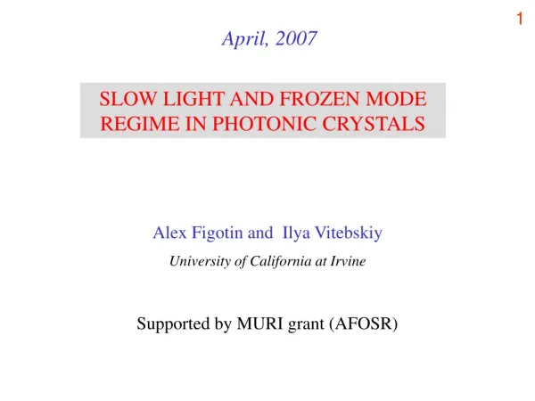
April, 2007 SLOW LIGHT AND FROZEN MODE REGIME IN PHOTONIC CRYSTALS Alex Figotin and Ilya Vitebskiy University of California at Irvine Supported by MURI grant (AFOSR)
2D periodicity 1D periodicity What are photonic crystals? Simplest examples of periodic dielectric arrays 1. Each constitutive component is perfectly transparent, while their periodic array may not transmit EM waves of certain frequencies. 2. Strong and controllable spatial dispersion, particularly at λ ~ L. 3. Photonic crystals should be treated as genuinely heterogeneous media – no “effective” homogeneous medium can imitate a photonic crystal.
(k) (k) (k) 1 1 k 2 2 k Typical kdiagramof a uniform anisotropic medium for a given direction of k.1and 2 are two polarizations. Typical kdiagramof an isotropic non-dispersive medium: = v k Typical kdiagram of a photonic crystal for a given direction of k. k Electromagnetic dispersion relation in photonic crystals
Each stationary point is associated with slow light, but there are some fundamental differences between these three cases.
Semi-infinite photonic crystal Transmitted slow mode Incident wave of frequency s Reflected wave What is the frozen mode regime? Example of a plane wave incident on a lossless semi-infinite photonic crystal - What happens if the incident wave frequency is equal to that of slow mode with vg= 0 ? - Will the incident wave be converted into the slow mode inside the photonic crystal, or will it be reflected back to space? Assuming that the incident wave amplitude is unity, let us see what happens if the slow mode is related to (1) RBE, (2) SIP, (3) DBE.
Assuming that the incident wave amplitude is unity, let’s see what happens if the slow mode is related to: (1) a regular band edge, (2) a stationary inflection point, or (3) a degenerate band edge.
ω g k Regular BE
ω 0 SIP case k
SIP Frozen mode profile at different frequencies close to SIP In all cases, the incident wave has the same polarization and unity amplitude.
ω d k DBE case
DBE Frozen mode profile at different frequencies close to DBE In all cases, the incident wave has the same polarization and unity amplitude.
ω ω ω g d 0 k k k Summary of the case of a plane wave incident on asemi-infinite photonic crystal supporting a slow mode. - The case of a regular BE: the incident wave is reflected back to space without producing slow mode in the periodic structure. - The case of a stationary inflection point: the incident wave can be completely converted into the slow mode with infinitesimal group velocity and huge diverging amplitude. - The case of a degenerate photonic BE: the incident wave is totally reflected back to space, but not before creating a frozen mode with huge diverging amplitude and vanishing energy flux. Regular band edge Stationary inflection point Degenerate band edge
Propagating mode: Im k = 0 Bloch eigenmodes Evanescent mode: Im k > 0 Evanescent mode: Im k < 0 Floquet mode: 01 (z) ~ z Non-Bloch eigenmode
A1A2FA1A2FA1 A2FA1A2F ω ω d 0 A1A2BA1A2BA1A2B L k k L What kind of periodic structures can support the frozen mode regime? SIP DBE
x Anisotropic layerA1 Anisotropic layerA2 Ferromagnetic layerF z y M|| z
2. Frozen mode regime in bounded photonic crystals So far we have discussed the frozen mode regime in lossless semi-infinite periodic structures. What happens to the frozen mode regime if the photonic crystal has finite dimensions?
EM wave incident on a finite photonic slab: different possibilities Photonic slab Different arrangements involving a photonic slab with finite thickness D = N L Photonic slab Mirror or absorber (a) (b) a) The incident wave is partially transmitted through the photonic slab. b) There is no transmitted wave if a mirror or an absorber is present. -------------------------------------------------------------------------------------------- We start with the case (a), involving incident, transmitted, and reflected waves. Then we turn to the case (b), where there is no transmitted wave at all.
Transmission band edge resonances near a regular photonic band edge (generic case) Finite stack transmission vs. frequency.ωg – regular photonic band edge Smoothed field intensity distribution at the frequency of first transmission resonance
Giant transmission band edge resonances near a degenerate photonic band edge Finite stack transmission vs. frequency.ωg – degenerate photonic band edge Smoothed Field intensity distribution at frequency of first transmission resonance
ω ω g d k k Regular BE vs. degenerate BE A stack of 10 layers with degenerate photonic BE performs as well as a stack of 100 layers with regular photonic BE !
RBE: Regular photonic band edge(Energy density ~ N2) DBE: Degenerate photonic band edge (Energy density ~ N4) Example: Transmission band edge resonance in periodic stacks of 8 and 16 double layers. Smoothed electromagnetic energy density distribution inside photonic cavity at frequency of transmission band edge resonance
Frozen mode profile at frequency of a giant transmission band edge resonance: a) with a mirror at the right-hand boundary, b) without the mirror.
Publications [1] A. Figotin and I. Vitebsky. Nonreciprocal magnetic photonic crystals.Phys. Rev. E 63, 066609, (2001) [2] A. Figotin and I. Vitebskiy. Electromagnetic unidirectionality in magneticphotonic crystals. Phys. Rev. B 67, 165210 (2003). [3] A. Figotin and I. Vitebskiy. Oblique frozen modes in layered media.Phys. Rev. E 68, 036609 (2003). [4] J. Ballato, A. Ballato, A. Figotin, and I. Vitebskiy. Frozen light in periodicstacks of anisotropic layers. Phys. Rev. E 71, 036612 (2005). [5] G. Mumcu, K. Sertel, J. L. Volakis, I. Vitebskiy, A. Figotin. RF Propagation in Finite Thickness Nonreciprocal Magnetic Photonic Crystals. IEEE: Transactions on Antennas and Propagation, 53, 4026 (2005) [6] A. Figotin and I. Vitebskiy. Gigantic transmission band-edge resonance inperiodic stacks of anisotropic layers. Phys. Rev. E72, 036619, (2005). [7] A. Figotin and I. Vitebskiy. Electromagnetic unidirectionality and frozen modesin magnetic photonic crystals. Journal of Magnetism and Magnetic Materials, 300, 117 (2006). [8] A. Figotin and I. Vitebskiy. "Slow light in photonic crystals" (Topical review),Waves in Random Media, Vol. 16, No. 3, 293 (2006). [9] A. Figotin and I. Vitebskiy. "Frozen light in photonic crystals with degenerate band edge". Phys. Rev. E74, 066613 (2006)
Fig. 2. Absorption versus frequency of a periodic stack with DBE at ω = ωd : (a) The vacuum – PS – mirror arrangement shown in Fig. 1(a). (b) The vacuum – PS – vacuum arrangement shown in Fig. 1(b). N = 8 is the number of unit cells in the periodic stack. Black and blue curves correspond to two different values of absorption coefficient γ of the isotropic B layers. In either case (a) or (b), larger absorption coefficient (the black curve) gives higher absorption peaks at frequencies of transmission band-edge resonances.
Frozen mode regime in the presence of negative absorption (one of the constitutive components is a gain medium). Transmission dispersion of a periodic stack with different values of negative absorption (gain) γ. Solid red curve corresponds to γ = 0. Observe the sharp difference between a regular TBER (just below ωa) and a giant TBER (just below ωd).
Transmission/reflection dispersion of a periodic stack with different values of negative absorption (gain) γ. Compared to the previous slide, the magnitude of negative absorption here is larger. The difference between the regular TBER (just below ωa) and the giant TBER (just below ωd) is now extreme.