Download
1 / 21
210 likes | 418 Vues
Wave Optics (Coincides with Ch. 22 in the book). Christian Huygens (XVII century) Based on his observations of waves on water, he formulated a very important law, known as the “Huygens Principle”. Huygens Principle: Any wavefront of a traveling wave can be

E N D
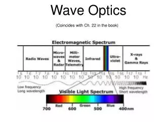
Wave Optics (Coincides with Ch. 22 in the book)
Christian Huygens (XVII century) Based on his observations of waves on water, he formulated a very important law, known as the “Huygens Principle”.
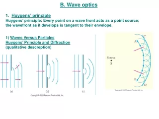
Huygens Principle: Any wavefront of a traveling wave can be replaced, as far as effects further along the propagation dire- ction are concerned, by a large number of “point sources” located uniformly all over the wavefront, radiating in phase.
Thomas Young’s 1805 experiment: according to the Huygens Principle, a narrow slit becomes a “point-like” source af a circular wave. Young demonstrated that light waves radiating from two narrow slits interfere, giving rise to a pattern of alternating bright and dark “stripes” on a screen. Original figure from Young’s 1805 report.
Soap Bubbles and Interference Filters The spectacular colors of soap bubbles are caused by destructive interference For instance: If for a certain wavelength the path traveled in the film by the wave is twice /4, this wavelength is removed from the reflected light. White light from which one pure color Is removed becomes a so-called “complementary color” – complemen- tary to the removed one. - = White minus green = magenta - = White minus red = cyan
The simplest interference filter: for one wavelength there is constructive interference between the transmitted wave, and the wave resulting from double reflection from both surfaces inside the film.
Grating (or “diffraction grating”). A plate with a large number of equally spaced narrow slits.
Grating: each of the many slits is the source of an elementary “Huygens wave”:
Plot explaining how the “zero-order” wave is produced: The incident plane wave
Here, the graph shows how the wave crests emerging from one slit interfere with the crests from the successive slits, phase-shifted by one full wavelength – thus forming the deflected wave “of the first order”. Of course, there is an analogous process for- ming a wave deflected to the right – but those wavefronts are not shown (the plot would become too messy, I’m afraid).
The first-order wave – a blown-up plot: d is the spacing between the grating’s slits. It is usually referred to as the “grating constant”. d The angle θ its propagation direction makes with the propagation direction of the incident beam can be readily obtained from basic trigonometry:
A graph explaining how the “second-order” deflected wave is created (a more appropriate term than “deflected” would be “diffracted”, but “deflection” is more intuitive). Now the wave crest emerging from one slit interferes with with the crest from the next slit that is phase- shifted by two wavelengths.
Diffraction by a single slit: there is a central maximum, and a num- Ber of weaker maxima (called “side-bands”) on both sides. The top plot explains where the minima between the side maxima are located (m in the for- mulae can take the value of 1, 2, 3…). Lower picture – single slit diffraction of red light from a laser pointer (an experiment one can easily make at home – a good slit can be made, e.g., from two disposable blades for standard box cutters).
Light diffraction on a single circular aperture (“aperture” is an elegant word meaning “hole”, or “opening”). Link to a good PPT presentation
The objective lens of a telescope can be thought of as a “circular opening”. Therefore, images of point objects (and distant stars are, in practice, “nearly point objects”) are not ideal points, but “discs” of the size of the central maximum in the diffraction pattern from such opening (continued in the next slide).
By astronomers, such diffraction-broadened images are called “Airy discs”. The Airy discs limit the ability of the telescope to resolve stars that are too close to each other in the sky. Let’s show this by considering a simple example. The opening of the largest OSU telescope has a 12 inch diame- ter (0.30 m). We can take the average wavelength in starlight as 500 nm. From the formula in the preceding slide we can calculate the angular size of the Airy disc in this telescope: This result means that any two objects in the skies, the “angular distance” between which is smaller than 0.4 second of arc, will merge in this teles- cope into a single “spot” – as illustrated by the rightmost blue shape in the preceding slide. This is a sufficient resolving power to see the Mizar A and Mizar B stars (we talked about them some tiime ago) as two separate objects, because the angular distance between them is 14 sec. of arc – but not two other stars in the five-star Mizar cluster. The effect of “Airy disc” also explains why astronomers want telescopes with objective diameters as large as possible!