Matter wave interferomery with poorly collimated beams
440 likes | 680 Vues
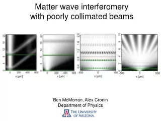
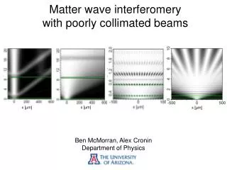
Matter wave interferomery with poorly collimated beams . Ben McMorran, Alex Cronin Department of Physics. x [µm]. x [µm]. main idea can get matter wave interference fringes with uncollimated beams but: grating position matters spatial coherence matters beam divergence matters

Matter wave interferomery with poorly collimated beams
E N D
Presentation Transcript
Matter wave interferomery with poorly collimated beams Ben McMorran, Alex Cronin Department of Physics x [µm] x [µm]
main idea can get matter wave interference fringes with uncollimated beams but: grating position matters spatial coherence matters beam divergence matters grating alignment matters we’ve got a way to model this
outline 1. partial coherence in grating interferometers 2. examples of grating matter wave interferometers Mach-Zehnder atom interferometer Talbot-Lau C60 interferometer Lau electron interferometer 3. grating alignment sensitivity 4. ideas for g measurement using uncollimated beam
partially coherent optical field complex degree of coherence µ(x) intensity I(x)
A Model for Partial Coherence and Wavefront Curvature in Grating Interferometers PRA (June 2008) … We simulate (1) the Talbot effect, (2) far-field diffraction, (3) Mach Zehnder interferometers (4) Talbot-Lau Interferometers (5) Lau interferometers …
Mutual Intensity Function: Intensity: (ρa ,z) (ρb ,z)
Mutual Intensity Function: Intensity: GSM: ρa ρb σ0 w0
Mutual Intensity Function: Intensity: GSM:
Mutual Intensity Function: Intensity: GSM: partially coherent Fresnel optics
AtomInterferometer • Objective:Pioneer new techniques using matter-wave interference to make precision measurements. • • Study quantum decoherence, • Matter-wave index of refraction, • Atomic polarizability. Approach:3 nano-fabricated diffraction gratings. • Mach-Zhender interferometer for atom-waves.. • Interferometer Performance: • • Up to 50% contrast. • Small phase drift (< 2 rad / hr). • • Layout is easily changed for • new experiments. • Macroscopic (100 mm) path separation.
gratings for matter waves 1.5µm 100nm
Optical Grating Second Grating
atom beam L = 1m skimmer Na α S1 = 10µm` S2 = 10µm v = 1km/s λ= 17pm α = (S1+S2)/L ~ 10-5 θdiff = λ/d ~ 10-4 ℓ= λL/S1 ~ 1µm
atom beam L = 1m skimmer Na α S1 = 10µm` S2 = 10µm ℓ > d coherent diffraction θdiff / α = 10 resolved diffraction but β = ℓ/S1 ~ 0.1 partially coherent “Gaussian Schell Source as Model for Slit-Collimated Atomic and Molecular Beams” McMorran, Cronin arXiv:0804.1162 (2008)
0 1 Atom Diffraction: 3 2 5 4 6 7 Atom Interference Fringes:
Atom fringes intensity
“Talbot-Lau fringes” add a second grating
“Matter-Wave Interferometer for Large Molecules” Brezger, Hackermüller, Uttenthaler, Petschinka, Arndt, Zeilinger Physical Review Letters 88 100404-1 (2002) L = 1.38m S2 = 0.5mm S1 = 1.2mm α ~ 10-3 θdiff ~ 10-6 ℓ~ 10nm
coarse fringes in the far field: “Lau fringes” add a second grating
electron interferometery with two gratings aperture magnetic lens grating 1 grating 2 stationary beam 1µm imaging detector α ~ 10-3 θdiff ~ 10-4ℓ~ 5nm Cronin and McMorran, PRA 74 (2006) 061602(R)
Lau interferometer G2 G1 incoherent source • each opening of G1 acts as a point source for a diffraction pattern from G2 • at certain grating separations, diffraction patterns overlap
Lau interferometer – fringe contrast vs. grating separation S ML y G1 x A G2 z CCD z12 z
Lau interferometer – fringe contrast vs. grating separation Cronin and McMorran, PRA 74 061602(R) (2006)
Lau interferometer –twist gratings to measure coherence y x G1 G2 z GSM source z0 z1 θ z2 z3 Lau fringe visibility
Lau interferometer – fringe contrast vs. grating rotation alignment sensitivity depends on coherence parallel to grating slits ℓ0 ≈ 10 nm
some figures: antihydrogen incident on 1µm period gratings 1m from source: v = 10 km/s: λ = 0.4Å S1 < 40µm for coherent diffraction (ℓ > d) v = 5 km/s: λ = 0.8Å S1 < 80µm v = 1 km/s: λ = 4.0Å S1 < 400µm T = 4K Δvx = 260m/s
position echo interferometer? position echo Mach-Zehnder
position echo interferometer? • fine-spaced interference fringes • precision for measuring deflection • uncollimated • more counts from wider slits • integrate across w • more counts looking at all paths
position echo interferometer? NEEDS FURTHER STUDY WITH REALISTIC PARAMETERS
conclusion • simulations + experiments: • matter wave fringes can be formed with uncollimated beams • necessary to think about partial coherence • less coherence parallel to slits contrast sensitive to grating misalignment • position echo behind 2 gratings useful for measure g? • we have a tool to model this