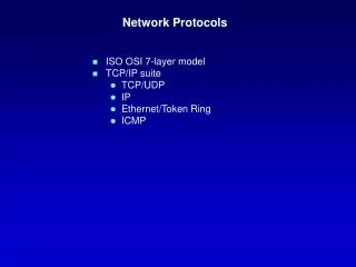
OSI Model: Communication Protocols Overview
Understand OSI model layers, protocols for communication network, Blade Center Technology, Virtual Machines. Explore Application, Presentation, Session, Transport layers.

OSI Model: Communication Protocols Overview
E N D
Presentation Transcript
Communication Network Protocols Brent R. Hafner CSC 8320
Agenda • OSI Protocols • Blade Center Technology • Virtual Machines • References
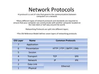
Application • The application layer is the OSI layer closest to the end user, which means that both the OSI application layer and the user interact directly with the software application. • This layer interacts with software applications that implement a communicating component. Such application programs fall outside the scope of the OSI model. Application layer functions typically include identifying communication partners, determining resource availability, and synchronizing communication. . • Some examples of application layer implementations include Telnet, File Transfer Protocol (FTP), and Simple Mail Transfer Protocol (SMTP), DNS, Web/Http.
Application (cont.) Client - Server Peer-to-Peer
Presentation • The presentation layer provides a variety of coding and conversion functions that are applied to application layer data. These functions ensure that information sent from the application layer of one system would be readable by the application layer of another system. Some examples of presentation layer coding and conversion schemes include common data representation formats, conversion of character representation formats, common data compression schemes, and common data encryption schemes.
Presentation Layer (cont.) • AFP, AppleShare File Protocol • GIF, GIF • ICA Citrix Systems Core Protocol][1] • JPEG, Joint Photographic Experts Group • LPP, Lightweight Presentation Protocol • NCP, NetWare Core Protocol • NDR, Network Data Representation • PNG, Portable Network Graphics • TIFF, Tagged Image File Format • XDR, eXternal Data Representation • X.25 PAD, Packet Assembler/Disassembler Protocol • Retrieved from "http://en.wikipedia.org/wiki/Presentation_layer"
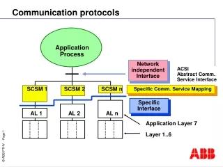
Session • The session layer implementation of the OSI protocol suite consists of a session protocol and a session service. The session protocol allows session-service users (SS-users) to communicate with the session service. An SS-user is an entity that requests the services of the session layer. Such requests are made at session-service access points (SSAPs), and SS-users are uniquely identified by using an SSAP address. Figure 30-4 shows the relationship between the SS-user, the SSAP, the session protocol, and the session service.
Session (cont.) Session service provides four basic services to SS-users. • Establishes and terminates connections between SS-users and synchronizes the data exchange between them. • Performs various negotiations for the use of session layer tokens, which the SS-user must possess to begin communicating. • Inserts synchronization points in transmitted data that allow the session to be recovered in the event of errors or interruptions. • Enables SS-users to interrupt a session and resume it later at a specific point.
Transport • The OSI protocol suite implements two types of services at the transport layer: connection-oriented transport service and connectionless transport service. Five connection-oriented transport layer protocols exist in the OSI suite, ranging from Transport Protocol Class 0 through Transport Protocol Class 4. Connectionless transport service is supported only by Transport Protocol Class 4.
Transport (cont.) • Transport Protocol Class 0 (TP0), the simplest OSI transport protocol, performs segmentation and reassembly functions. TP0 requires connection-oriented network service. • Transport Protocol Class 1 (TP1) performs segmentation and reassembly, and offers basic error recovery. TP1 sequences protocol data units (PDUs) and will retransmit PDUs or reinitiate the connection if an excessive number of PDUs are unacknowledged. TP1 requires connection-oriented network service. • Transport Protocol Class 2 (TP2) performs segmentation and reassembly, as well as multiplexing and demultiplexing of data streams over a single virtual circuit. TP2 requires connection-oriented network service. • Transport Protocol Class 3 (TP3) offers basic error recovery and performs segmentation and reassembly, in addition to multiplexing and demultiplexing of data streams over a single virtual circuit. TP3 also sequences PDUs and retransmits them or reinitiates the connection if an excessive number are unacknowledged. TP3 requires connection-oriented network service. • Transport Protocol Class 4 (TP4) offers basic error recovery, performs segmentation and reassembly, and supplies multiplexing and demultiplexing of data streams over a single virtual circuit. TP4 sequences PDUs and retransmits them or reinitiates the connection if an excessive number are unacknowledged. TP4 provides reliable transport service and functions with either connection-oriented or connectionless network service. It is based on the Transmission Control Protocol (TCP) in the Internet Protocols suite and is the only OSI protocol class that supports connectionless network service.
Network Layer The network layer provides the functional and procedural means of transferring variable length data sequences from a source to a destination via one or more networks while maintaining the quality of service requested by the transport layer. The Network layer performs network routing, flow control, network segmentation/desegmentation, and error control functions i.e. P (IPv4 • IPv6) • ARP • RARP • ICMP • IGMP • RSVP • IPSec • • datagram network provides network-layer connectionless service • VC network provides network-layer connection service • analogous to the transport-layer services, but: • service: host-to-host • no choice: network provides one or the other • implementation: in network core
Network Layer (cont.) Virtual Networks Datagram Networks no call setup at network layer routers: no state about end-to-end connections no network-level concept of “connection” packets forwarded using destination host address packets between same source-dest pair may take different paths • used to setup, maintain teardown VC • used in ATM, frame-relay, X.25 • not used in today’s Internet
Data Link • The data link layer provides reliable transit of data across a physical network link. Different data link layer specifications define different network and protocol characteristics, including physical addressing, network topology, error notification, sequencing of frames, and flow control. Physical addressing (as opposed to network addressing) defines how devices are addressed at the data link layer. Network topology consists of the data link layer specifications that often define how devices are to be physically connected, such as in a bus or a ring topology. Error notification alerts upper-layer protocols that a transmission error has occurred, and the sequencing of data frames reorders frames that are transmitted out of sequence. Finally, flow control moderates the transmission of data so that the receiving device is not overwhelmed with more traffic than it can handle at one time.
“link” Data Link (cont.)
Data Link (cont.) The Logical Link Control (LLC) sublayer of the data link layer manages communications between devices over a single link of a network. LLC is defined in the IEEE 802.2 specification and supports both connectionless and connection-oriented services used by higher-layer protocols. IEEE 802.2 defines a number of fields in data link layer frames that enable multiple higher-layer protocols to share a single physical data link. The Media Access Control (MAC) sublayer of the data link layer manages protocol access to the physical network medium. The IEEE MAC specification defines MAC addresses, which enable multiple devices to uniquely identify one another at the data link layer.
Physical The physical layer defines the electrical, mechanical, procedural, and functional specifications for activating, maintaining, and deactivating the physical link between communicating network systems. Physical layer specifications define characteristics such as voltage levels, timing of voltage changes, physical data rates, maximum transmission distances, and physical connectors. Physical layer implementations can be categorized as either LAN or WAN specifications. Figure 1-7 illustrates some common LAN and WAN physical layer implementations.
Load Balancing Architecture Workload management is often deployed to proactively shift workload on the basis of the current state of the system, server, and/or networking metrics. This can be done at Level 4 or Level 7 in the OSI model. For example, consider a service whose Domain Name Server (DNS) name is Service_A.com. Normally, there would be a server set up somewhere with that host name and IP address. With Layer 4 switching, the switch module itself takes ownership of the IP address as a VIP and has multiple ‘‘real’’ server blades behind it capable of delivering the service Service_A.com, whose addresses can be arbitrarily assigned, since they are of only local significance.
Virtual Servers – VMWare ESX ESX Server installs on the “bare metal” and allows multiple unmodified operating systems and their applications to run in virtual machines that share physical resources. Each virtual machine represents a complete system, with processors, memory, networking, storage and BIOS. Advanced resource allocation policies for virtual machines allow you to guarantee resources to even your most resource-intensive applications.
Virtual Machines (cont.) As shown in Figure 8, each of the server blades can support virtual machine (VM) technology, such as VMware** virtual infrastructure [34–36], in order to share the blade physical resources by hosting multiple instances of OS images. In addition to the blade being shared, the networking infrastructure can also be shared with the use of VLAN technology, and security can be maintained between VMs. For example, each VM shown in Figure 8 can be logically associated with an independent VLAN configured on the switch, so that with three VMs per blade, there could be a total of 3 3 m total VLANs configured internally and trunked out to the uplinks of the switch.
References • S. W. Hunter, N.C. Strole, D.W. Crosby, and D.M Greene ‘‘BladeCenter Networking’’, IBM J Res & Dev, November 2005; see http://www.research.ibm.com/journal/rd/496/hunter.pdf • Jim Kurose, Keith Ross, Computer Networking: A Top Down Approach Featuring the Internet, 3rd edition. Addison-Wesley, July 2004. • Cisco Systems, OSI Network Protocols, October 2006; see http://www.cisco.com/univercd/cc/td/doc/cisintwk/ito_doc/osi_prot.htm#wp1022221 • VMWare, ESX Server 3.0; see http://www.vmware.com/products/vi/esx/