Voltage Regulators: Linear and Switching Types in Electronics
Learn about voltage regulators used to maintain power levels within tolerance and protect electronic components, including linear and switching types. Explore advantages, disadvantages, and characteristics of different regulator designs. Discover the operation principles of switching regulators and considerations for optimal performance in electronic circuits.

Voltage Regulators: Linear and Switching Types in Electronics
E N D
Presentation Transcript
Voltage Regulators • Used to regulate input voltage from a power source • Maintains power level to within set tolerance • Prevents damage to components by acting as a buffer • Two types: Linear and Switching
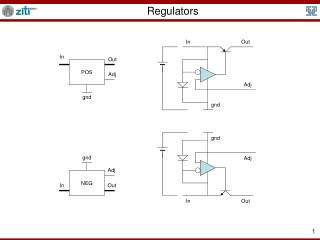
Linear Regulators • Acts like a voltage divider • Uses FET in ohmic region
Switching Regulator • Switches on and off rapidly to alter output • Requires Control Oscillator and charge storage components
Types of Switching Regulators • Buck (step down) - lowers input • Boost (step up) - raises input • Buck / Boost - lowers/raises/inverts input depending on needs and controller • Charge Pump – provides multiples of input without using any inductors
Linear Advantages • Simple • Low output ripple voltage • Excellent line and load regulation • Fast response time to load or line changes • Low electromagnetic interference (less noise)
Linear Disadvantages • Low efficiency • Large space requirement if heatsink is needed • Can not increase voltage above the input
Switching Advantages • High Efficiency • Capable of handling higher power densities • Structures can provide output that is greater than, less than or spanning the input voltage
Switching Disadvantages • Higher output ripple voltage • Slower transient recovery time • EMI is produced (Very noisy) • Generally more costly
Linear RegulatorsDarlington NPN Regulator • Dropout= 2Vbe + Vsat; Typically 1.5-2.5Vdc
PNP LDO Regulator • Dropout= Vsat; Typically <500mV. • At light loads, this falls to 10-20mV.
Quasi-LDO Regulator • Dropout= Vbe + Vsat.
Linear Regulators • Two Considerations Ground Pin Current (Ignd), Vdo (Dropout Voltage At light loads, this falls to 10-20mV. • Here, Ignd= IL/β (Pass Transistor Gain) • Darlington’s high gain allow Ignd= a few mA (typically) • Quasi-LDO, good performance (source 3A @ <10mA) • LDO, Ignd= 10-20mA, which can be up to 7% of IL • All are unconditionally stable (requires no external capacitors)
P-FET LDO Regulator • Advantageous because the amount of PWR dissipated is Vin * Ignd, because of the Pass FET’s low “on” voltage (~.7-.8V), only a small current is required to maintain regulation.
Switching Regulators – Overview • Operation relies on controlled transfer of charge from input to output. • Output node charges while switch is closed and discharges while switch is open. • Requires multi-part circuitry. • Storage of the charge to be transferred. • Control of switching scheme. • Output-stage filtering
Switching Regulators – Pulse Rate Modulation • Constant duty cycle • Varying frequency • Noise spectrum imposed by PRM varies and is more difficult to filter out.
Switching Regulators – Pulse Width Modulation • Constant frequency • Varying duty cycle • Preferred – Efficient and easy to filter out noise.
Switching Regulator – Continuous Mode • Current through inductor never drops to zero. • Allows for highest output power for a given input voltage, switching scheme and switch current rating. • Overall performance is better.
Switching Regulator – Discontinuous Mode • Current through inductor drops to zero during each cycle. • Allows for smaller inductor and thus smaller overall circuit size. • Better when output current is low.
Switching Topologies Dielectric isolation vs. non-isolating • NI: Uses – small change in Vout/Vin • DI: Uses – radiation-intense environments • Ideally Power in = Power out
Non-Isolating forms • Examples include: Buck, Boost, Buck/Boost, Cuk, Charge Pump
Isolated types • Examples include: Flyback converters and Forward Converters
Other Considerations for Switchers • MOSFETs and Diodes • Synchronous Rectification – Getting more Efficiency • Operating Frequencies
Ideal Inductors Purely Inductive
Real Inductors SRF Inductive Capacitive Resistive
Frequency-Dependence for Switching Regulators • The frequency-dependent effects limit the inductor to a useful range of frequencies. • Usually the SRF (Self-Resonant Frequency) is specified by the manufacturer. • This sets a hard upper limit. The useful limit is generally lower.
High Frequencies are Good • As a general rule of thumb, doubling the switching frequency allows halving the inductance. • An old DC-DC converter at 30kHz might need an inductor measuring 1” in diameter. • A modern converter operating at 1MHz can deliver the same current with an inductor measuring less than .25” in diameter. • A smaller inductor will have a smaller series resistance.
Series Resistance • Series resistance increases losses. • It can also lead to instability in boost configurations. Duty Cycle Duty Cycle
Series Resistance - Solutions • Current sensing / overcurrent protection • Duty cycle limiting Duty Cycle
Cores and Saturation • Magnetic cores increase the magnetic flux density when an external field is applied, increasing energy storage capacity and inductance. • When a core is saturated, increasing the external magnetic field results in a negligible increase in flux density. 1μm No External Field In an External Field
Cores and Saturation • The onset of saturation can occur very rapidly. • At saturation, the effective inductance decreases dramatically. • This decrease can lead to instability (increasing duty cycle, decreasing inductance). • Without current or duty cycle limiting, this can result in catastrophic failure. • The manufacturer will usually specify this as the DC saturation current, the point where the inductance reaches 10% of nominal.
Cores and Saturation B • Cores also exhibit losses due to internal “friction” and eddy currents. • In switchers, these losses are usually only a small percentage of the total losses, even at saturation. • However, saturation in a DC-DC supply can cause greater resistive losses due to the drop in inductance. H
Important Parameters • Inductance: Larger inductances have lower ripple current, but are larger and can decrease stability. • Peak Current: This is obtained from the switcher’s datasheet. • DC Current: Dependent on load requirements. • SRF: Should be well above the switcher’s operating frequency. • Series Resistance: Affects the efficiency and can affect stability.
Applications and Sample Circuits of Some Common Packages • National Instruments LM337 Package • 3-terminal adjustable regulator • Capable of supplying 1.2V to 37V with 1.5A • Offers overload protection that is only available in ICs • Can also be used as a precision current regulator • Texas Instruments TPS32xx Package • Optimal for battery powered portable applications. • Operates a 93% efficiency at 3MHz.
Simple LM117 Voltage Regulator Configuration • 1.2V to 25V output • C1 is only needed if the device is more that 6” from the filter capacitors. • C2 is optional – it is used to improve the transient response.
5V Logic Regulator with Electronic Shutdown • Uses TTL for electronic shutdown. • Clamping of adjustment terminal programs the output to 1.2V where most loads draw little current. • 1.2V is the minimum output voltage.
0V to 30V Regulator • The downside is that the full output current is not available for high input/output voltages.
Precision Current Limiter • Iout = Vref/R1 • 0.8 Ohms < R1 < 120 Ohms
AC Voltage Regulator • Regulates a 24Vp-p Input to 12Vp-p at 1A.
12V Battery Charger • Rs is used to set the output impedance of the charger:
Texas Instruments TPS62300 • Used in low-power portable electronics • Designed for fast start-up time
References • TI. Understanding Buck Power Stages in Switchmode Power Supplies. http://focus.ti.com/lit/an/slva057/slva057.pdf. • TI. Understanding Boost Power Stages in Switchmode Power Supplies. http://focus.ti.com/lit/an/slva061/slva061.pdf. • Erickson, R. DC-DC Power Converters. http://ece-www.colorado.edu/~rwe/papers/Encyc.pdf. • Shen, L., Kong, J. Applied Electromagnetism, Third Edition. • http://www.web-ee.com/primers/files/f5.pdf • http://www.maxim-ic.com/appnotes.cfm/appnote_number/710/ln/en • http://www.eetasia.com/ARTICLES/2000NOV/2000NOV30_AMD_AN2.PDF