Jang-Hui Han, DESY
200 likes | 362 Vues
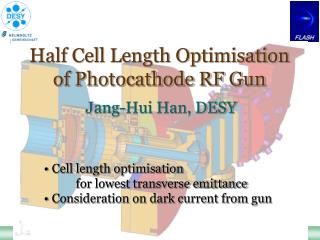
Half Cell Length Optimisation of Photocathode RF Gun. Jang-Hui Han, DESY. Cell length optimisation for lowest transverse emittance Consideration on dark current from gun. RF Gun Schematic. 1.5 cell L-band RF gun (1.3 GHz). Photocathode. Electron beam. Bucking solenoid.

Jang-Hui Han, DESY
E N D
Presentation Transcript
Half Cell Length Optimisation of Photocathode RF Gun Jang-Hui Han, DESY • Cell length optimisation • for lowest transverse emittance • Consideration on dark current from gun
RF Gun Schematic 1.5 cell L-band RF gun (1.3 GHz) Photocathode Electron beam Bucking solenoid Coaxial RF coupler Main solenoid Half Cell Length Optimization of Photocathode RF Gun
Operating phase Phase Dependence of Ebeam Half Cell Length Optimization of Photocathode RF Gun
Average Beam Energy 45 MV/m 40 MV/m At cathode ~ 0 MeV At the first iris ~ 2 MeV At the exit ~ 4.5 MeV Most important for beam quality Half Cell Length Optimization of Photocathode RF Gun
~ 0.68 mm mrad (rrms = 0.55 mm) at FLASH Eemit~ sin 35 x 42 (MV/m) ~ 24 MV/m / laser size rms ~1.24 mm mrad / mm Thermal Emittance • Measurement with • laser temporal distribution • ~ 3 ps rms Gaussian • laser spot size ~ 0.55 mm • bunch charge ~ 3 pC E = Emax sin Half Cell Length Optimization of Photocathode RF Gun
trans Vs Half Cell Length ASTRA simulation with 50000 macro particles 45 MV/m at cathode Half cell length longitudinal (fixed) 2 ps rise/fall 20 ps fwhm transverse radius variable Half Cell Length Optimization of Photocathode RF Gun
trans Vs Half Cell Length 40 MV/m at cathode 50 MV/m at cathode Half Cell Length Optimization of Photocathode RF Gun
trans Vs Half Cell Length 55 MV/m at cathode 60 MV/m at cathode Half Cell Length Optimization of Photocathode RF Gun
Gun (50 MV/m) + Linac Thermal emittance (therm = 0.5 mm mrad) included assuming Ekin = 0.55 eV Half Cell Length Optimization of Photocathode RF Gun
Gun (50 MV/m) + Linac Half Cell Length Optimization of Photocathode RF Gun
Emission Phase Variation Half Cell Length Optimization of Photocathode RF Gun
Field Emission (Dark Current) Dark current after gun Field emission Vs RF phase Half Cell Length Optimization of Photocathode RF Gun
Dark Current Source (c) (d) (b) (a) The maxima of the rf field strength can be the major source of dark current ASTRA simulation at 40 MV/m max field and 300 A main solenoid current Half Cell Length Optimization of Photocathode RF Gun
Dark Current & Beam Momentum measurement at PITZ simulation with ASTRA PITZ: Photoinjector Test Facility at DESY, Zeuthen Half Cell Length Optimization of Photocathode RF Gun
Dark Current at 60 MV/m Dark current at the entrance of the 1st module dark current reduced by 63% half cell length 65 75 mm Very small overlap in the momentum spectra Half Cell Length Optimization of Photocathode RF Gun
Dark Current (Simulation) Dark current starts from the cathode area (2 mm rms) ASTRA simulation with 100 000 macro-particles Particle tracked up to 10 m downstream including aperture Half Cell Length Optimization of Photocathode RF Gun
Summary • Beam transverse emittance calculated for cavities with different half cell length. • Transverse emittance shows no big difference for 64 – 70 mm first cell length. • With increasing first cell length, dark current separated from beam. Half Cell Length Optimization of Photocathode RF Gun
RF Field Profile Calculated by Microwavestudio Half Cell Length Optimization of Photocathode RF Gun
Dark Current & Beam Images y = 3 mm drive-laser 16 mm Dark current image 5 mm y = 0 mm laser spot (0.44 mm rms) Mo y = 2 mm Cs2Te y mirror scan x Electron beam movement on the dark current image By the influence of the solenoid field the trajectory of the beam rotates by ~90. Half Cell Length Optimization of Photocathode RF Gun
(2) (1) (3) Bunch Charge Vs RF Phase Operating condition for min. transverse ~ max. momentum Electron bunch is emitted with a combination of several factors • Space charge force dominated emission + longitudinal laser profile • Schottky effect dominated emission • Beam dynamics after the emission and aperture <Gun parameters> Bunch charge: 1 nC at 35 Laser parameter: [temporal] ~20 ps flat top [transverse] ~0.55 mm rms RF gradient: 45 MV/m Cathode: Cs2Te with 60 nm Main solenoid: 320 A Bucking solenoid: 24 A Half Cell Length Optimization of Photocathode RF Gun