Jang-Hui Han Diamond Light Source
200 likes | 369 Vues
Design of a Low Emittance and High Repetition Rate Photoinjector Towards Ultimate Optimisation with Mature S-band Technologies. Jang-Hui Han Diamond Light Source. Success of NC Guns and Possible Next Steps.

Jang-Hui Han Diamond Light Source
E N D
Presentation Transcript
Design of a Low Emittance and High Repetition Rate PhotoinjectorTowards Ultimate Optimisation with Mature S-band Technologies Jang-Hui Han Diamond Light Source Ultra Brightness Electron Sources Workshop, Cockcroft Institute, 2011
Success of NC Guns and Possible Next Steps • Great successes of LCLS S-band gun and PITZ L-band gun: 1 mm mrad emittance at 1 nC has been broken and low charge options allow 0.2 – 0.4 mm mrad emittace • Can we further improve injector performance? • Gun cavity geometry • Position of gun solenoid • Position of first accelerating section Ultra Brightness Electron Sources Workshop, Cockcroft Institute, 2011
Low Emittance e-beam for XFEL System layout: - RF gun (120 MV/m) + focusing solenoids - 4 accelerating cavities (3.1 m) + solenoids Ultra Brightness Electron Sources Workshop, Cockcroft Institute, 2011
Laser Profile and Thermal Emittance for Simulations Temporal profile Flat top with 1 ps rise/fall time (10% to 90%) Length (fwhm): 8 ps for 200 pC 4 ps for 20 pC Radial profile Uniform distribution with sharp edge Radius is variable for optimisation Thermal emittance 0.6 eV kinetic energy of photo-emitted electrons 0.89 mm mrad per 1 mm (rms) initial beam size(th~r) Ultra Brightness Electron Sources Workshop, Cockcroft Institute, 2011
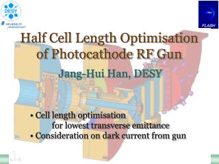
Gun Geometry Optimisation – Cell Length 1st cell 2nd cell S-band (2.998 GHz) LCLS S-band (2.856 GHz) 1st cell: 33.782 mm (0.6432 /2) 2nd cell: 53.0606 mm (1.0103 /2) Optimum lengths? PITZ (FLASH) L-band (1.3 GHz) 1st cell: 65.05 mm (0.5638 /2) 2nd cell: 120.05 mm (1.0404 /2) Ultra Brightness Electron Sources Workshop, Cockcroft Institute, 2011
Gun Cell Length Vs Emittance for 2.998 GHz gun Scaled LCLS 2.856 GHz gun Scaled DESY 1.3 GHz gun Projected transverse emittance at the gun exit, simulated using ASTRA 200 pC beam, 8 ps laser length, 120 MV/m at cathode 2nd cell: 0.5 1st cell: scanning from 0.23 to 0.33 of minimum at 0.27 or 0.28 Ultra Brightness Electron Sources Workshop, Cockcroft Institute, 2011
Gun Solenoid Position at FLASH and LCLS FLASH L-band gun Coaxial coupler Main solenoid around the gun gun solenoid LCLS S-band gun Side coupler Gun solenoid downstream of the gun Where the optimum solenoid position? Ultra Brightness Electron Sources Workshop, Cockcroft Institute, 2011
Gun (Main) Solenoid Position Optimisation Projected transverse emittance at the gun exit, simulated using ASTRA 200 pC, 8 ps laser, 120 MV/m at cathode LCLS gun this design Variable main solenoid position Ultra Brightness Electron Sources Workshop, Cockcroft Institute, 2011
Effect of Gun Solenoid Position When the gun solenoid is placed nearer to the cathode, the beam size can be controlled to be smaller. Ultra Brightness Electron Sources Workshop, Cockcroft Institute, 2011
1st Accelerating Section Position FLASH (5 MeV) Cathode to 1st section: 2.7 m Euro-XFEL (7 MeV) Cathode to 1st section: 3.4 m LCLS (5 MeV) Cathode to 1st section: 1.5 m Where the optimum position? Ultra Brightness Electron Sources Workshop, Cockcroft Institute, 2011
Effect of 1st Accelerating Section Position 1st section at 1.0 m Transverse emittance: 0.194 mm mrad 1st section at 1.8 m Transverse emittance: 0.135 mm mrad 200 pC beam, 8 ps laser pulse with 1 ps rise/fall 120 MV/m peak field at the cathode Simulation using ASTRA Ultra Brightness Electron Sources Workshop, Cockcroft Institute, 2011
Beam Parameters at 200 pC and 20 pC 200 pC 20 pC Ultra Brightness Electron Sources Workshop, Cockcroft Institute, 2011
Possible Further Step with Improved Laser/Cathode With reduced thermal emittance, Projected emittance 0.08 mm mrad Slice emittance 0.07 mm mrad C.P. Hauri et al., Phys. Rev. Lett. 104, 234802 (2010) If the kinetic energy of photoelectrons (thermal emittace) is reduced 0.6 eV (0.89 mm mrad per 1 mm rms) 0.15 eV (0.45 mm mrad per 1 mm rms) (th~ Ek) Ultra Brightness Electron Sources Workshop, Cockcroft Institute, 2011
Summary of Low Emittance Injector Design • Gun cell length • Accelerating field strength during beam emission • Emittance reduction by 8% • Gun solenoid position • Beam size control • Emittance reduction by 30% • 1st accelerating section position • Optimum beam matching • Emittance reduction by 40% • Factor of 2 reduction of normalised transverse emittance compared to the LCLS gun 0.135 mm mrad at 200 pC • If the kinetic energy of photo-emitted electrons can be reduced from 0.6 eV to 0.15 eV, 0.08 mm mrad at 200 pC may be possible! Ultra Brightness Electron Sources Workshop, Cockcroft Institute, 2011
Gun Design for Low Emittance and High Rep. Rate RF in Basically the same design as the PITZ/FALSH guns with a reduced size to the S-band (3 GHz) Electron beam Drive laser RF Power Coupler Design (CST Studio) Ultra Brightness Electron Sources Workshop, Cockcroft Institute, 2011
Cold Test with a Prototype 0 mode 21 MHz mode Design Prototype for cold tests with a network analyser Measurement Ultra Brightness Electron Sources Workshop, Cockcroft Institute, 2011
Cooling-Water Channel ANSYS simulation assuming 17 kW average RF power 17 kW: 5.7 MW peak power (100 MV/m) 3 s 1 kHz 8.2 MW peak power (120 MV/m) 3 s 700 Hz 16C water with 3 m/s flow through cooling channels Max 50C at the central iris, cylindrical symmetry Ultra Brightness Electron Sources Workshop, Cockcroft Institute, 2011
ANSYS Results with 17 kW – Deformation and Stress Max 43m deformation Cylindrical symmetry The same radial deformation at the 1st (half) and 2nd (full) cells 17 kW produces a von Mises stress of 50 MPa at the corner of the cell Ultra Brightness Electron Sources Workshop, Cockcroft Institute, 2011
Coupler Thermal Analysis Ultra Brightness Electron Sources Workshop, Cockcroft Institute, 2011
Summary of Gun Design • Coaxial RF coupler allows: • Perfect axial symmetry of RF field • Improved water cooling • Axial symmetric thermal deformation • Optimum gun solenoid position • Reliable thermal behaviour • Very low heating/stress at the RF coupling region • Thermally stable up to 700 Hz at 120 MV/m or 1 kHz at 100 MV/m • New S-band gun is under production • To be delivered in August • To be tested with high power RF (but low repetition rate) Ultra Brightness Electron Sources Workshop, Cockcroft Institute, 2011