Download
1 / 18
180 likes | 351 Vues
The ground calibration of the back-side illuminated CCD camera of XIS onboard Astro-E2 (Suzaku). H. Yamaguchi , H. Nakajima, H. Matsumoto, T. G. Tsuru, K. Koyama (Kyoto Univ., Japan), D. Matsuura, T. Miyauchi, S.Katsuda, M. Namiki, K. Torii, K. Hayashida,

E N D
The ground calibration of the back-side illuminated CCD camera of XIS onboard Astro-E2 (Suzaku) H. Yamaguchi, H. Nakajima, H. Matsumoto, T. G. Tsuru, K. Koyama (Kyoto Univ., Japan), D. Matsuura, T. Miyauchi, S.Katsuda, M. Namiki, K. Torii, K. Hayashida, H. Tsunemi (Osaka Univ., Japan), and XIS team
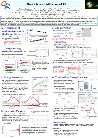
Contents • Introduction Characteristic of XIS-BI • Event Detection Grade method • Charge Trailing Charge trailing against the transfer. We developed “Charge Trail Correction”. • Onboard Calibration Comparison with Chandra/ACIS
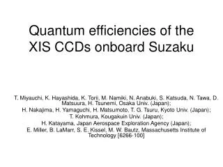
1. Introduction XIS : Front-illuminated (FI) CCD×3 + Back-illuminated (BI) CCD×1 Suzaku (Astro-E2) BI-CCD‥ High quantum efficiency for soft X-ray XIS-FI XIS-BI Quantum efficiency of XIS XIS sensor
1. Introduction back surface X-ray Charge cloud spreads widely ↓ Energy resolution become worse spread ex. Chandra/ACIS ΔE(BI) ≒ 2×ΔE(FI) electrode Chemisorption charging process strengthen the electric field Collection efficiency of electrons were improved !! structure of XIS-BI
1. Introduction Spectrum of O-K line counts/keV XIS-BI XIS-FI Energy resolution of the XIS-BI is almost comparable with FI! ΔE= 49eV (BI) 42eV (FI) @0.53keV ΔE= 129eV (BI) 128eV (FI) @5.9keV
1. Introduction Ground Calibration Task Share
Grade0 Grade1 Grade2 Grade3 Grade4 Grade5 Grade6 Grade7 2. Event Detection Grade02346 are used as X-ray event We analyzed BI data similarly to FI. ↓ Several problems were found. split over 2x2 region The center pixel A pixel whose PH is larger than split threshold and added to the PHA (= summed PH) A pixel whose PH is larger than split threshold but NOT added to the PHA
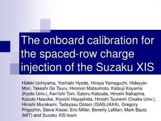
3. Charge Trailing Ground Calibration Imaging Area of XIS Vertical Uniform illumination of fluorescent X-ray transfer Read out node Distribution of Grade0,2,3,4,6 events Distribution of Grade7events Several X-ray events escape to Grade7? Counts Counts not uniform! V (Vertical) V (Vertical)
3. Charge Trailing transfer transfer transfer Trailing charge Contribute to the increasing Grade0 Grade2 Vertical Some charges are deposited during the transfer. PH Grade0 Grade2
3. Charge Trailing transfer transfer Distribution of Grade7events Counts V (Vertical) PH transfer Grade6 Grade7 Trailing charge
3. Charge Trailing extracted only Mn-K event Trailing Charge ≡ Q’[ADU] Q’ (ADU) V Q’ = C×N ; C = 6.8×10⁻³ N (Number of transfer) spectrum of Mn-K “Charge Trail Ratio” (CTR) ≡ the probability of charge trailing par 1 pixel transfer Mean PHA ≡Q[ADU] CTR [1/transfer] = C/Q CTR = 4.5×10⁻⁶ @5.9keV (Mn-K)
3. Charge Trailing We have developed “Charge Trail Correction”. V V Before After CTR depends on the PHA of event Relation of the CTR and the PHA is able to be expressed by the power-law function CTR CTR = (1.72×10⁻⁴)×(PHA[ADU])-0.5 Q (PHA)
3. Charge Trailing After the Charge Trail Correction … Distribution of Grade0,2,3,4,6 events Counts not uniform! V (Vertical) Distribution of Grade0,2,3,4,6 events becomes uniformly. Grade7 events due to charge trail are successfully reduced. → The detection efficiency improve about 10-20%.
4. Spilt Threshold Optimization Split threshold = 20ADU (for XIS-FI) XIS-FI (SpTh.= 20ADU) XIS-BI (SpTh.= 20ADU) 20ADU is not optimum value of the split threshold for BI?
4. Spilt Threshold Optimization O-K (0.5keV) Zn-K (8.6keV) ΔE (eV) Efficiency Split Threshold (ADU) Split Threshold (ADU) O-K line optimum split threshold 10ADU for 0.5keV 13ADU for 8.6keV Zn-K line Split Threshold (ADU)
4. Spilt Threshold Optimization Optimize the split threshold for each energy events The function for setting split threshold optimum split threshold [ADU] = 10.359 + 2.2075 log10(E [keV] ) we make Grade classification using variable split threshold Energy resolution of the XIS-BI is almost comparable with FI ΔE= 49eV (BI) 42eV (FI) @0.53keV XIS-FI (SpTh.= 20ADU) XIS-BI (SpTh.= 20ADU) XIS-BI (variable SpTh.) ΔE= 129eV (BI) 128eV (FI) @5.9keV
5. Onboard Calibration Spectra of E0102-72 XIS FI XIS BI ACIS BI XIS keeps their performance even after the launch!!
Summary • Suzaku/XIS is composed of 3 FI-CCD and 1 BI-CCD. • Good energy resolution of BI was achieved by chemisorption charging process. • We developed new analysis method, “Charge Trail Correction”. → Detection efficiency improved. • More detailed onboard calibration is proceeding now.