
MR Compatibility
E N D
Presentation Transcript
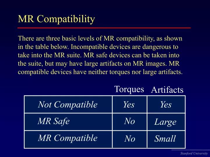
MR Compatibility There are three basic levels of MR compatibility, as shown in the table below. Incompatible devices are dangerous to take into the MR suite. MR safe devices can be taken into the suite, but may have large artifacts on MR images. MR compatible devices have neither torques nor large artifacts. Torques Artifacts Not Compatible Yes Yes MR Safe No Large MR Compatible No Small
Typical artifacts Arrowhead artifact obtained when the needle is | B0 and the image plane is | to the needle. Artifacts obtained when the imaging plane is || to the needle. These images show typical needle artifacts for three different needles. Also shown is an egg (left) and a bottle of oil (right). The needles are placed through a perforated plastic sheet, seen in the lower images.
Needle artifacts overview Factors that affect the artifact on MR images include: • Magnetic susceptibility of the material (c) • Size of device • Field strength of the MR scanner • RF refocusing • Orientation of the needle wrt Bo • Orientation of frequency encoding direction • Receive bandwidth, if an RF-refocused sequence is used • Echo Time, if a gradient recalled echo sequence is used In the following pages, you can find examples of most of these effects.
Magnetic susceptibility All materials have a property called magnetic susceptibility (c). Devices of ferromagnetic materials are generally incompatible. Some non-magnetic stainless steels are MR safe. Paramagnetic materials such as titanium are MR compatible. Alloys such as Inconel have a net magnetic susceptibility in the mid para- magnetic range. A longer list of magnetic susceptiblities can be found in Schenk et al. Med Phys. Diamagnetic Paramagnetic Ferromagnetic Diamagnetic Paramagnetic Ferromagnetic Magnetic Magnetic T itanium T itanium Water Stainless Steel Stainless Steel 5 10 5 10 1 10 -5 -2 10 1 -1 -1 -10 -10 -5 -10 -2 -5 -1 -1 -10 -10 -10 -5 'Nonmagnetic' 'Nonmagnetic' Copper Stainless Steel Pure Iron Stainless Steel Pure Iron
Material and size This picture is pretty self explanatory. Gauge: 22 20 18 16 14 Stainless Steel High Ni, low c alloy Inconel Titanium alloy
Field strength Artifacts are bigger at higher field strength, as you can see in the images below. These were taken with the same receive bandwidth. Not only are the in-plane shifts larger at the higher field stregth, but there is also more potato-chipping of the slice around the needles at high field. This results in signal modulation in the lower left image. 0.5T 1.5T
RF refocusing With gradient echo sequences, there is signal dropout. With RF refocused sequences, the artifact is more complicated and interesting. Mostly, images from an RF refocused sequence (FSE) are shown in this presentation. GRE FSE Freq | Needle FSE freq || Needle
Orientation wrt/ B0 The needle orientation wrt/ B0 has a huge effect on the artifact. In the top row, the needle is perpendicular to B0, while in the bottom row, the needle is parallel to B0. In the needle parallel to B0 orientation, the needle shaft is perfectly depicted, while there is artifact off the end of the needle. Off resonance spins are shifted in the direction of frequency encoding.
Frequency encoding direction When frequency encoding is along the direction of the needle, the spins are distorted along the length of it (grey arrows). This is evident by the distortion of the perforated plastic sheet. When frequency encoding is perpendicular to the needle, the artifact is broadened.
Receive bandwidth Higher receive bandwidths reduce the artifact on RF-refocused sequences.
Receive bandwidth Again, higher receive bandwidths result in a smaller artifact on rf-refocused sequences. In gradient echo sequences, there is signal dropout dependent on echo time and independent of the BW. Bandwidth 4 32 64 8 16 SE FSE SPGR
Echo time in GRE These images mimic echo times of .5 ms, 1 ms and 2 ms. This was done by offsetting the gradient recalled echo from the spin echo. The piling up artifact is progressively more dephased with echo offset, just as it would be with longer echo time GRE.
Example incompatible needle artifact These examples were acquired with a GRE sequence. Incompatible 21g needle Compatible 21g needle MR Compatible Trocar
View angle tilting View angle tilting (VAT) compensates for shifts of off-resonance spins during readout with shifts during slice selection. Signal appears to be registered properly. VAT does not compensate for potato chipping of the slice. That’s why the needle artifact isn’t perfectly circular in the lower right picture.