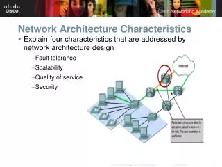
Network Architecture
Network Architecture. Objectives of Lecture. Show how network architecture can be understood using a layered approach. Introduce the OSI seven layer reference model. Introduce the concepts of internetworking and routing. Understand the difference between network protocols and services.

Network Architecture
E N D
Presentation Transcript
Objectives of Lecture • Show how network architecture can be understood using a layered approach. • Introduce the OSI seven layer reference model. • Introduce the concepts of internetworking and routing. • Understand the difference between network protocols and services. CINS/F1-01
Contents 1.1 Extended example: how the Internet protocols fetch a web page 1.2 The concept of protocol layering 1.3 Internetworking and routing 1.4 The OSI seven layer model
Protocols • The term protocol refers to a well-known set of rules and formats to be used in order to perform a task. For example, a task of communicating between processes. • Parts of a protocol: • A specification of a sequence of messages that must be exchanged. • A specification of the format of the data in the messages. • Existence of well-known (standard) protocols enables the separate components of the distributed systems to be developed independently in different languages and on different platforms.
Four elements of a protocol: A set of rules governing the communication between two peer entities. It must define the format and the order of messages as well as actions taken on the transmission and receipt of a message. • syntax: format, what is a valid message? • “GET /~hugue/index.html HTTP/1.1\nHOST: www.cs.umd.edu\n\n” • Semantics: what does it mean? • Get file /~hugue/index.html using the http 1.1 protocol. • Action: • read file /~hugue/index.html from the disk, send it through the socket using the http 1.1 protocol and close the socket • Timing: relative order of messages. • Reply follows the request
1.1 Internet Protocols Network Web Browser Web Server
Four-Layer Model Distributed data communications involves three primary components: • Applications • Computers • Networks Four corresponding layers • Application layer • Transport layer • Internet layer • Network Interface
Basic Internet Network Architecture Host A Host B Application Layer Application Layer HTTP Message Transport Layer Transport Layer TCP Packet Router Internet Layer Internet Layer Internet Layer IP Datagram IP Datagram Network Layer Network Layer Network Layer Ethernet Frame Ethernet Frame Physical Network Physical Network
Application Layer • How does a web browser retrieve data from a web server? • Application Protocol: Hypertext Transfer Protocol (HTTP). • Users invoke applications which “speak” using application protocol. • Applications interact with a transport protocol to send or receive data. • Other applications: FTP, SMTP, DNS, SMB, …
Application Layer Example • HTTP outline: • GET /~hugue/index.html HTTP/1.1 • Host: www.cs.umd.edu GET /~hugue/index.html HTTP/1.1 Host: www.cs.umd.edu HTTP Message
Transport Layer • Provides end-to-end communication between applications. • Transport Protocol: Transport Control Protocol (TCP) • a reliable, connection-oriented transport protocol. • Divides stream of application messages into packets. • Interacts with Internet Layer to send or receive data. • In general, a transport protocol may be • reliable or unreliable, • connection-oriented or connectionless, • and flow may or may not be regulated. • Others: UDP, ICMP.
Transport Layer Example • TCP outline: • Source Port: 1081 • Destination Port: 80 • Checksum: 0xa858 Src: 1081 Dst: 80 Chksum: 0xa858 GET /~hugue/index.html HTTP/1.1 Host: www.cs.umd.edu TCP header HTTP Message
Internet Layer • Responsible for routing communications between one machine and another. • Accepts requests to send packets to destination address. • Internet Protocol (IP) encapsulates packets in IP datagram with IP header and uses routing algorithm to decide whether to send directly or indirectly. • Also handles incoming IP datagrams. • If addressed to local machine, remove the IP datagram header and pass up to transport layer.
Internet Layer Example • IP outline: • Time to live: 128 • Header checksum: 0x57d1 • Source: my home pc (69.140.128.222) • Destination: www.cs.umd.edu (128.8.10.143) IP datagram header TCP header HTTP Message Src: 69.140.128.222 Dst: 128.8.10.143 TTL: 128 Src: 1081 Dst: 80 Chksum: 0xa858 GET /~hugue/index.html HTTP/1.1 Host: www.cs.umd.edu
Network Interface Layer • Accepts IP datagrams and transmits over specific networks. • Maybe a simple device driver (e.g. an Ethernet driver) or a complex subsystem with further data link protocols.
Network Interface Layer Example • Ethernet outline: • Destination: 00:a0:cc:54:1d:4e • Source: 00:e0:81:10:19:fc • Type: IP Ethernet Frame Src: 00:e0:81:10:19:fc Dst: 00:a0:cc:54:1d:4e Type: IP Src: 69.140.128.222 Dst: 128.8.10.143 TTL: 128 Src: 1081 Dst: 80 Chksum: 0xa858 GET /~hugue/index.html HTTP/1.1 Host: www.cs.umd.edu
Ports and Addresses • Ports are destination points within a host computer. • Processes are attached to the ports, enabling them to communicate. • Transport layer addresses are composed of network address of the host computer and a port number. • In the Internet every host is assigned a unique IP number which is used in routing. • In an Ethernet each host is responsible for recognizing that the messages meant for it.
1.2 Protocol Layering Host A Host B Application Layer Application Layer Message Transport Layer Transport Layer Packet Internet Layer Internet Layer Datagram Network Interface Network Interface Frame Physical Network
Protocol Layering Web Browser Web Server Application Layer Application Layer HTTP Message Transport Layer Transport Layer TCP Packet Internet Layer Internet Layer IP Datagram Network Layer Network Layer Ethernet Frame Physical Network
Protocol Hierarchies • Protocols are stacked vertically as series of ‘layers’. • Each layer offers services to layer above, shielding implementation details. • Layer n on one machine communicates with layer n on another machine (they are peer processes/entities) using Layer n Protocol.
Layers, Protocols & Interfaces Layer n/n+1 interface Layer n/n+1 interface Layer n protocol Layer n Layer n Layer n-1/n interface Layer n-1/n interface Layer 2/3 interface Layer 2/3 interface Layer 2 protocol Layer 2 Layer 2 Layer 1/2 interface Layer 1/2 interface Layer 1 protocol Layer 1 Layer 1 Physical communications medium
Layer/Interface Design • Important objective is ‘clean’ interfaces, having minimal set of well-defined services. • Clean-cut interfaces enable: • minimisation of inter-layer communications • easy replacement of individual layers • Set of layers and protocols is the Network Architecture.
Virtual & Actual Communications • Important to understand difference between: • virtual and actual communications, • protocols and interfaces. • Peer processes ‘think’ of communications as being ‘horizontal’ using protocol. • Actual communications is via interfaces (and the physical communications medium). • Peer process idea is key to network design.
Design Issues • Some issues affect many layers, e.g: • need to address data (say who it’s for), • possible need for setting up connections, • data transfer rules (simplex, half-duplex, ...), • error management, • deal with message component re-ordering, • flow control, • routing • security
1.3 Internetworking and Routing • No single networking technology can satisfy all requirements. • Universal interconnection is desired. • Protocols allow communication between nodes without understanding underlying mechanisms. • Internetworking is the process by which a group of disparate, heterogeneous networks can be linked to form a single logical network. • The Internet is just such a collection.
Routing Routing is the mechanism used to transfer data between networks to reach the correct destination. Network B Router Web Browser Network A Routing takes place at the IP layer: routers are not aware of transport and application layers. Web Server
Protocol Layering and Routing Host A Host B Application Layer Application Layer HTTP Message Transport Layer Transport Layer TCP Packet Router Internet Layer Internet Layer Internet Layer IP Datagram IP Datagram Network Layer Network Layer Network Layer Ethernet Frame Ethernet Frame Physical Network Physical Network
1.4 The OSI Reference Model • OSI Reference Model – an internationally standardised network architecture. • An abstract representation of an ideal network protocol stack; not used in real networks. • OSI = Open Systems Interconnection. • Specified in ISO 7498-1. • Model has 7 layers.
Internet Protocols vs OSI Application Application 7 Presentation 6 5 Session 5 TCP Transport 4 4 3 IP Network 3 Network Interface 2 Data Link 2 Hardware Physical 1 1
The OSI Model Layer 7 Application Layer Layer 6 Presentation Layer Layer 5 Session Layer Layer 4 Transport Layer Layer 3 Network Layer Layer 2 Data Link Layer Layer 1 Physical Layer
Lower/Upper Layers • Layers 1-4 often referred to as lower layers. • Layers 5-7 are the upper layers. • Lower layers relate more closely to the communications technology. • Layers 1 – 3 manage the communications subnet. • the entire set of communications nodes required to manage massages between a pair of machines. • Layers 4 – 7 are true ‘end-to-end’ protocols. • Upper layers relate to application.
Layer 7: Application Layer • Home to wide variety of protocols for specific user needs, e.g.: • virtual terminal service, • file transfer, • electronic mail, • directory services.
Layer 6: Presentation Layer • Concerned with representation of transmitted data. • Deals with different data representations. • ASCII or EBCDIC, • one’s complement or two’s complement, • byte ordering conventions, • floating point conventions (IEEE or proprietary). • Also deals with data compression.
Layer 5: Session Layer • Allows establishment of sessions between machines, e.g. to • allow remote logins • provide file transfer service. • Responsible for: • dialogue control • which entity sends when with half-duplex communications. • token management • E.g. control which entity can perform an operation on shared data. • synchronisation • E.g. insertion of checkpoints in large data transfers.
Layer 4: Transport Layer • Basic function is to take data from Session Layer, split it up into smaller units, and ensure that the units arrive correctly. • Concerned with efficient provision of service. • The Transport Layer also determines the ‘type of service’ to provide to the Session Layer.
Layer 3: Network Layer • Key responsibility is control of routing in the subnet. • Routing can be based on: • static tables, • determined at start of session, • highly dynamic (varying for each packet depending on network load). • Also responsible for congestion control and usage monitoring.
Layer 2: Data Link Layer • Provides reliable, error-free service on top of raw Layer 1 service. • Breaks data into frames. Requires creation of frame boundaries. • Frames used to manage errors via acknowledgements and selective frame retransmission.
Layer 1: Physical Layer • Concerned with bit transmission over physical channel. • Issues include: • definition of 0/1, • whether channel simplex/duplex, • connector design. • Mechanical, electrical, procedural matters.
Services in the OSI Model • In OSI model, each layer provide services to layer above, and ‘consumes’ services provided by layer below. • Active elements in a layer are called entities. • Entities in same layer in different machines are called peer entities.
Layering Principles n+1 PDU (n+1) Entity Service User (n+1) Entity Service User Layer n+1 protocol Layer n Service Access Point (SAP) SDU (n) Entity Service Provider (n) Entity Service Provider Layer n protocol N-1 PDU N-1 PDU PDU - Protocol Data Unit SDU - Service Data Unit
Services and Protocols • Service = set of primitives provided by one layer to layer above. • Service defines what layer can do (but not how it does it). • Protocol = set of rules governing data communication between peer entities, i.e. format and meaning of frames/packets. • Service/protocol decoupling very important.
Connections • Layers can offer connection-oriented or connectionless services. • Connection-oriented like telephone system. • Connectionless like postal system. • Each service has an associated Quality-of-service (e.g. reliable or unreliable).
Reliability Issues • Reliable services never lose/corrupt data. • Reliable service costs more. • Typical application for reliable service is file transfer. • Typical application not needing reliable service is voice traffic. • Not all applications need connections.
VERS HL TOS Fragment Length Datagram ID FLAG Fragment Offset TTL Protocol Header Checksum Source Address Destination Address Options (if any) Data IP datagram • IP Addresses • Logical, unique • eg. cs.umd.edu is 128.8.10.143 • IP Packet Format:
TCP Segment Format Source Port Destination Port Sequence Number Request Number offset Reser. Control Window Checksum Urgent Pointer Options (if any) Data
Source Port Destination Port Length Checksum Data UDP Datagram Format
Sockets Programming • Network API • Socket Structures • Socket Functions
Network Application Programming Interface (API) • The services provided by the operating system that provide the interface between application and protocol software. Application NetworkAPI Protocol A Protocol B Protocol C