Download
1 / 19
190 likes | 315 Vues
Network Architecture. IS250 Spring 2010 John Chuang chuang@ischool.berkeley.edu. Network Abstracted as Cloud. Network utility: ping. Network. client server. A. 1. B. 2. Hosts. Links. 4. 3. or local. C. networks. 5. D. 6. E. Routers. Network as Routers & Links.

E N D
Network Architecture IS250 Spring 2010 John Chuang chuang@ischool.berkeley.edu
Network Abstracted as Cloud • Network utility: ping Network client server John Chuang IS250 UC Berkeley
A 1 B 2 Hosts Links 4 3 or local C networks 5 D 6 E Routers Network as Routers & Links Source: Coulouris, Dollimore and Kindberg Network utility: traceroute/tracert John Chuang IS250 UC Berkeley
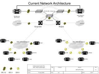
Inter-exchange Carrier (IXC) Long- Distance Network Interconnected Networks Customer Premises Internet Service Providers Telephone Network Internet backbones Point of Presence Backbone Provider 1 Router Router Tandem Switch Dial-Up ISP Local Exchange Carrier (LEC) Exchange Point DNS Local Egress Switch Router Server Local Ingress Switch Content Provider Packet Network Local Loop Headend Backbone Provider 2 Cable Network Remote ISP Analog Modem xDSL Modem Router router Cable Modem Firewall Client Corporate LAN John Chuang IS250 UC Berkeley Wireless ISP Terminal
A 2x2 Network Model John Chuang IS250 UC Berkeley
Network Building Blocks • Transmission media • Copper (coax, twisted pair), optical fiber, free space (wireless) • Signals • Electrical currents, light, RF (radio-frequency), microwave • Hardware devices • End hosts, network interfaces • Routers, switches, hubs, bridges, repeaters • Software components • Communication protocol stack John Chuang IS250 UC Berkeley
Network Architecture • Networking can be quitecomplex and requires a high degree of cooperation between the involved parties. • Cooperation is achieved by forcing parties to adhere to a set of rules and conventions (protocol). • The complexity of the communication task is reduced by using multiple protocol layers: • Each layer is implemented independently. • Each layer is responsible for a specific subtask. • Layers are grouped in a hierarchy. • A structured set of protocols is called a network architecture, protocol architecture, or protocol suite. John Chuang IS250 UC Berkeley
Layering • Layering: a technique of organizing a network system into logically distinct entities such that the service provided by one entity is based on the service provided by a lower level entity • Service: what a layer does • Interface: how to access the service • Protocol: how the service is implemented • Set of rules and formats governing communication between two peers John Chuang IS250 UC Berkeley
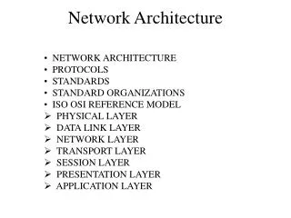
Application layer Layer 7 Presentation layer Layer 6 Session layer Layer 5 Transport layer Layer 4 Network layer Layer 3 Data link layer Layer 2 Physical layer Layer 1 ISO/OSI Reference Model What each layer does • Application (layer 7): specific to application need • Presentation (layer 6): conversion of data representation • Session (layer 5): access mgt, synchronization • Transport (layer 4): end-to-end delivery, congestion and flow control • Network (layer 3): addressing, routing • Data Link (layer 2): framing, error detection • Physical (layer 1): bits (0/1), voltages, frequencies, wires, pins, … John Chuang IS250 UC Berkeley
Application layer Application layer Layer 7 Layer 7 Software Presentation layer Layer 6 Socket API Transport layer Session layer Layer 5 Layer 4 Transport layer Layer 4 Operating System Network layer Network layer Layer 3 Layer 3 Data link layer Layer 2 Layer 2 Link layer Hardware Physical layer Physical layer Layer 1 Layer 1 TCP/IP Model ISO/OSI Reference Model Layered Protocol Architecture John Chuang IS250 UC Berkeley
Example: The “IP Hourglass” A single protocol John Chuang IS250 UC Berkeley
Why Layers? • Modularity • Divide and conquer: easier to design • Mix and match • Single network supports heterogeneous applications over heterogeneous networks • e.g., Voice-over-IP, IP-over-fiber, IP-over-wireless • Abstraction • Changes isolated • A layer can be changed without affecting upper/lower layers • Disadvantages of layering? John Chuang IS250 UC Berkeley
end-to-end Appl Appl end-to-end Trans port Trans port point-to-point Net work Net work Net work Net work point-to-point Link Link Link Link Host A Router 1 Router 2 Host B TCP/IP Model John Chuang IS250 UC Berkeley
TCP/IP Model end-to-end Appl Appl end-to-end Trans port Trans port point-to-point Net work Net work Net work Net work point-to-point Link Link Link Link Host A Router 1 Router 2 Host B John Chuang IS250 UC Berkeley
TCP/IP Model end-to-end Appl Appl end-to-end Trans port Trans port point-to-point Net work Net work Net work Net work point-to-point Link Link Link Link Host A Router 1 Router 2 Host B John Chuang IS250 UC Berkeley
Message Flow Appl Appl Trans port Trans port Net work Net work Net work Net work Link Link Link Link Host A Router 1 Router 2 Host B John Chuang IS250 UC Berkeley
EncapsulationExample: Sending HTTP message using TCP/IP over Ethernet HTTP message port HTTP message TCP header TCP segment TCP IP header IP datagram/packet Ethernet header IP Ethernet frame Adapted from Coulouris, Dollimore and Kindberg John Chuang IS250 UC Berkeley
Encapsulation Data Appl Appl Data Trans port Trans port Net work Net work Data Net work Net work Data Link Link Link Link Host A Router 1 Router 2 Host B John Chuang IS250 UC Berkeley
Summary • Networking is a complex problem: geographic distribution; diverse ownership; heterogeneous technologies and applications • Abstraction helps in the analysis and design of networks • Layered architecture supports abstraction and modularity • Encapsulation: clear separation of layer-specific functionalities; isolation between layers • Hourglass: a single network layer protocol connects multiple networks; supports different applications over different underlying network technologies John Chuang IS250 UC Berkeley