Distributed Systems Concepts
Distributed Systems Concepts. Ch. 10 and 14-17. Figure 10.1 Skew between computer clocks in a distributed system. m. r. m. t. p. Time server,S. Figure 10.2 Clock synchronization using a time server. 1. 2. 2. 3. 3. 3.

Distributed Systems Concepts
E N D
Presentation Transcript
Distributed Systems Concepts Ch. 10 and 14-17
Figure 10.1Skew between computer clocks in a distributed system
m r m t p Time server,S Figure 10.2Clock synchronization using a time server
1 2 2 3 3 3 Note: Arrows denote synchronization control, numbers denote strata. Figure 10.3An example synchronization subnet in an NTP implementation
Server B T T i -2 i-1 Time m m' Time Server A T T i - 3 i Figure 10.4Messages exchanged between a pair of NTP peers
Figure 10.6Lamport timestamps for the events shown in Figure 10.5
Figure 10.7Vector timestamps for the events shown in Figure 10.5
Figure 10.10Chandy and Lamport’s ‘snapshot’ algorithm • Marker receiving rule for process pi • On pi’s receipt of a marker message over channel c: • if (pi has not yet recorded its state) it • records its process state now; • records the state of c as the empty set; • turns on recording of messages arriving over other incoming channels; • else • pi records the state of c as the set of messages it has received over c • since it saved its state. • end if • Marker sending rule for process pi • After pi has recorded its state, for each outgoing channel c: • pi sends one marker message over c • (before it sends any other message over c).
Figure 10.13Reachability between states in the snapshot algorithm
Figure 10.14Vector timestamps and variable values for the execution of Figure 10.9
Chapter 11,12, and 13 • Are on transaction an concurrency control that are typically covered in a data base course.
Figure 14.1A basic architectural model for the management of replicated data Requests and replies RM RM C FE Clients Front ends Service Replica C FE RM managers
Group address expansion Leave Group send Multicast Group membership Fail communication management Join Process group Figure 14.2Services provided for process groups
a (allowed). b (allowed). p crashes p crashes p p q q r r view (q, r) view (q, r) view (p, q, r) view (p, q, r) c (disallowed). d (disallowed). p crashes p crashes p p q q r r view (q, r) view (q, r) view (p, q, r) view (p, q, r) Figure 14.3View-synchronous group communication
Primary RM C FE RM Backup C FE RM Backup Figure 14.4The passive (primary-backup) model for fault tolerance
RM C FE RM FE C RM Figure 14.5Active replication
Figure 15.2The window of scarcity for computing and communication resources
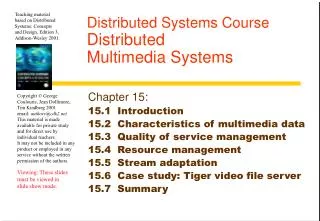
Data rate Sample or frame (approximate) size frequency Telephone speech 64 kbps 8 bits 8000/sec CD-quality sound 1.4 Mbps 16 bits 44,000/sec Standard TV video 120 Mbps up to 640 x 480 24/sec (uncompressed) pixels x 16 bits Standard TV video 1.5 Mbps variable 24/sec (MPEG-1 compressed) HDTV video 1000–3000 Mbps up to 1920 x 1080 24–60/sec (uncompressed) pixels x 24 bits HDTV video 10–30 Mbps variable 24–60/sec MPEG-2 compressed) Figure 15.3Characteristics of typical multimedia streams
Figure 15.4Typical infrastructure components for multimedia applications
Component Bandwidth Latency Loss rate Resources required Out: 10 frames/sec, raw video Zero Camera 640x480x16 bits A Codec In: 10 frames/sec, raw video Interactive Low 10 ms CPU each 100 ms; Out: MPEG-1 stream 10 Mbytes RAM B Mixer In: 2 44 kbps audio Interactive Very low 1 ms CPU each 100 ms; Out: 1 44 kbps audio 1 Mbytes RAM H Window In: various Interactive Low 5 ms CPU each 100 ms; system Out: 50 frame/sec framebuffer 5 Mbytes RAM K Network In/Out: MPEG-1 stream, approx. Interactive Low 1.5 Mbps, low-loss connection 1.5 Mbps stream protocol L Network In/Out: Audio 44 kbps Interactive Very low 44 kbps, very low-loss connection stream protocol Figure 15.5QoS specifications for components of the application shown in Figure 15.4
Protocol version Maximum transmission unit Token bucket rate Token bucket size Maximum transmission rate Minimum delay noticed Maximum delay variation Loss sensitivity Burst loss sensitivity Loss interval Quality of guarantee Figure 15.8The RFC 1363 Flow Spec Bandwidth: Delay: Loss:
Figure 15.9Filtering Source Targets High bandwidth Medium bandwidth Low bandwidth
Figure 15.10Tiger video file server hardware configuration Controller low-bandwidth network 0 n+1 1 n+2 2 n+3 3 n+4 n 2n+1 Cub 0 Cub 1 Cub 2 Cub 3 Cub n high-bandwidth ATM switching network Start/Stop requests from clients video distribution to clients
block service 2 1 0 t time block play time T slot 0 slot 1 slot 2 slot 3 slot 4 slot 5 slot 6 slot 7 viewer 4 free free viewer 0 viewer 3 viewer 2 free viewer 1 state state state state state Figure 15.11Tiger schedule
Figure 16.2Mether system program - slide 1 #include "world.h" struct shared { int a,b; }; Program Writer: main() { struct shared *p; methersetup(); /* Initialize the Mether run-time */ p = (struct shared *)METHERBASE; /* overlay structure on METHER segment */ p->a = p->b = 0; /* initialize fields to zero */ while(TRUE) { /* continuously update structure fields */ p –>a = p –>a + 1; p –>b = p –>b - 1; } } Continued on next slide...
Figure 16.2Mether system program - slide 2 Program Reader: main() { struct shared *p; methersetup(); p = (struct shared *)METHERBASE; while(TRUE) { /* read the fields once every second */ printf("a = %d, b = %d\n", p –>a, p –>b); sleep(1); } }
Figure 17.1IDL interfaces Shape and ShapeList struct Rectangle{ 1 long width; long height; long x; long y; } ; struct GraphicalObject { 2 string type; Rectangle enclosing; boolean isFilled; }; interface Shape { 3 long getVersion() ; GraphicalObject getAllState() ; // returns state of the GraphicalObject }; typedef sequence <Shape, 100> All; 4 interface ShapeList { 5 exception FullException{ }; 6 Shape newShape(in GraphicalObject g) raises (FullException); 7 All allShapes(); // returns sequence of remote object references 8 long getVersion() ; };
Figure 17.2Java interface ShapeList generated by idltojava from CORBA interface ShapeList public interface ShapeList extends org.omg.CORBA.Object { Shape newShape(GraphicalObject g) throws ShapeListPackage.FullException; Shape[] allShapes(); int getVersion(); }
Figure 17.3ShapeListServant class of the Java server program for CORBA interface ShapeList import org.omg.CORBA.*; class ShapeListServant extends _ShapeListImplBase { ORB theOrb; private Shape theList[]; private int version; private static int n=0; public ShapeListServant(ORB orb){ theOrb = orb; // initialize the other instance variables } public Shape newShape(GraphicalObject g) throws ShapeListPackage.FullException { 1 version++; Shape s = new ShapeServant( g, version); if(n >=100) throw new ShapeListPackage.FullException(); theList[n++] = s; 2 theOrb.connect(s); return s; } public Shape[] allShapes(){ ... } public int getVersion() { ... } }
Figure 17.4Java class ShapeListServer import org.omg.CosNaming.*; import org.omg.CosNaming.NamingContextPackage.*; import org.omg.CORBA.*; public class ShapeListServer { public static void main(String args[]) { try{ ORB orb = ORB.init(args, null); 1 ShapeListServant shapeRef = new ShapeListServant(orb); 2 orb.connect(shapeRef); 3 org.omg.CORBA.Object objRef = orb.resolve_initial_references("NameService"); 4 NamingContext ncRef = NamingContextHelper.narrow(objRef); NameComponent nc = new NameComponent("ShapeList", ""); 5 NameComponent path[] = {nc}; 6 ncRef.rebind(path, shapeRef); 7 java.lang.Object sync = new java.lang.Object(); synchronized (sync) { sync.wait();} } catch (Exception e) { ... } } }
Figure 17.5Java client program for CORBA interfaces Shape and ShapeList import org.omg.CosNaming.*; import org.omg.CosNaming.NamingContextPackage.*; import org.omg.CORBA.*; public class ShapeListClient{ public static void main(String args[]) { try{ ORB orb = ORB.init(args, null); 1 org.omg.CORBA.Object objRef = orb.resolve_initial_references("NameService"); NamingContext ncRef = NamingContextHelper.narrow(objRef); NameComponent nc = new NameComponent("ShapeList", ""); NameComponent path [] = { nc }; ShapeList shapeListRef = ShapeListHelper.narrow(ncRef.resolve(path)); 2 Shape[] sList = shapeListRef.allShapes(); 3 GraphicalObject g = sList[0].getAllState(); 4 } catch(org.omg.CORBA.SystemException e) {...} }
server client implementation interface repository repository skeleton object adapter Request ORB client proxy Servant ORB program for A core A core Reply or dynamic invocation or dynamic skeleton Figure 17.6The main components of the CORBA architecture
Figure 17.7IDL module Whiteboard module Whiteboard { struct Rectangle{ ...} ; struct GraphicalObject { ...}; interface Shape { ...}; typedef sequence <Shape, 100> All; interface ShapeList { ...}; };
Type Examples Use sequence typedef sequence <Shape, 100> All; Defines a type for a variable-length typedef sequence <Shape> All sequence of elements of a specified bounded and unbounded sequences IDL type. An upper bound on the o f Shapes length may be specified. string String name; Defines a sequences of characters, typedef string<8> SmallString; terminated by the null character. An unbounded and bounded upper bound on the length may be sequences of characters specified. array typedef octet uniqueId[12]; Defines a type for a multi-dimensional fixed-length sequence of elements of a typedef GraphicalObject GO[10][8] specified IDL type. Figure 17.8IDL constructed types – 1 this figure continues on the next slide
Type Examples Use record struct GraphicalObject { Defines a type for a record containing a string type; group of related entities. Structs are Rectangle enclosing; passed by value in arguments and boolean isFilled; results. }; enumerated enum Rand The enumerated type in IDL maps a (Exp, Number, Name); type name onto a small set of integer values. union union Exp switch (Rand) { The IDL discriminated union allows case Exp: string vote; one of a given set of types to be passed case Number: long n; as an argument. The header is parameterized by an enum , which case Name: string s; specifies which member is in use. }; Figure 17.8 IDL constructed types – 2
IOR format IDL interface type name Protocol and address details Object key interface repository IIOP host domain port number adapter name object name identifier name Page 684CORBA interoperable object references