Download
1 / 49
801 likes | 1.53k Vues
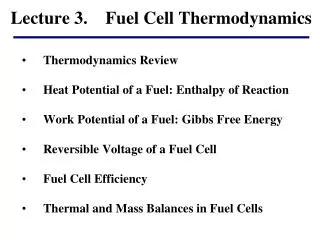
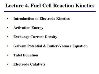
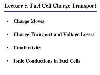
Lecture 5. Fuel Cell Charge Transport . Charge Moves Charge Transport and Voltage Losses Conductivity Ionic Conductions in Fuel Cells. Fuel Cell Performance Curve. Reversible Voltage (Chapter 2). Activation Loss (Lecture 4). Ohmic Loss (Lecture 5). Cell voltage(V). Cell voltage(V).

E N D
Lecture 5. Fuel Cell Charge Transport • Charge Moves • Charge Transport and Voltage Losses • Conductivity • Ionic Conductions in Fuel Cells
Fuel Cell Performance Curve Reversible Voltage (Chapter 2) Activation Loss (Lecture 4) Ohmic Loss (Lecture 5) Cell voltage(V) Cell voltage(V) Cell voltage(V) Current Density (A/cm2) Current Density (A/cm2) Current Density (A/cm2) Concentration Loss (Lecture 6) Net Fuel Cell Performance Cell voltage(V) Cell voltage(V) Current Density (A/cm2) Current Density (A/cm2)
Ohmic Losses Transp. Losses Transp. Losses 4 2 2 4 1 3 3 1 Ohmic Losses Rxn Losses Rxn Losses Fuel in Air in Flowstructure Porous electrode Anode Electrolyte Cathode
Charges Move in Response to Forces zi is the charge number for the carrier A JA A
e- e- H+ e- H+ e- H+ H2 H+ O2 e- H+ e- H+ e- H+ Anode Electrolyte Cathode
e- H+ H2 H+ O2 e- H+ e- H+ e- H+ Anode Electrolyte Cathode Voltage (V) hohmic Eo V
Example 4.1 A 10-cm2 PEMFC employs an electrolyte membrane with conductivity of 0.1 -1cm-1. For this fuel cell, Relec has been determined to be 0.005 . Assuming only other contribution to cell resistance comes from the electrolyte membrane, determine the voltage loss (ohmic) for the fuel cell at a current density of 1 A/cm2 in the following cases: (a) the electrolyte membrane is 100 m thick; (b) the electrolyte membrane is 50 m thick.
Example 4.1 Solution: i=j*A = 1 (A/cm2) * 10 (cm2) = 10 (A) Case (a): Rionic= L/(A) = 0.01 /(0.1 *10) = 0.01 () =10(0.005+0.01) = 0.15 (V) Case (b): Rionic= L/(A) = 0.005 /(0.1 *10) = 0.005 () =10(0.005+0.005) = 0.10 (V)
1.2 Cell voltage(V) 0.5 Current (A) 1.0 FC Charge Transport Resistance “V = iR” for fuel cells Theoretical EMF or Ideal voltage Ohmic Loss: hohmic= iRohmic Rohmic = 0.50 W Rohmic = 0.75 W Rohmic = 1.0 W Current, not current density!
Area Specific Resistance (ASR) • Fuel cell performance is evaluated with j-V curves, not i-V curves • But, hohmic = iR • Therefore, to use j instead of i, use ASR instead of R • hohmic = jASR (j = i/A so hohmic = iR = jA*R = jASR)
ASR Example (4.2) Calculate the the ohmic voltage losses for both fuel cells. Which one incurs the larger ohmic voltage loss? j = 1 (A/cm2 ) 1 2 A1 = 1 cm2 R1 = 0.1 A2 = 10 cm2 R2 = 0.02
ASR Example (4.2) j = 1 (A/cm2 ) 1 2 A1 = 1 cm2 R1 = 0.1 ASR1= 0.1 cm2 1,ohmic= j*ASR1 = 0.1 (V) A2 = 10 cm2 R2 = 0.02 ASR2= 0.2 cm2 2,ohmic= j*ASR2 = 0.2 (V)
Ionic Resistance Dominates ASR = L/ Ionic conductivity is orders of magnitude lower than electrical conductivity of metals, so minimizing the resistance of fuel cell electrolyte is essential. Several practical issues have be considered when reducing the electrolyte resistance. 1). Mechanical integrity; 2). Nonuniformity; 3). Shorting; 4). Fuel crossover; 5). Contact resistance; 6). Dielectric breakdown.
Ionic Conductions in Electrolyte • A good electrolyte must meet the following requirements: • High ionic conductivity • Low electronic conductivity • High stability (oxidizing and reducing) • Low fuel crossover • Reasonable mechanical strength (if solid) • Ease of manufacturability
Ionic Conductivity in Aqueous Electrolyte/Ionic Liquids Example 4.3. Calculate the approximate conductivity of 0.1 M aqueous solution of KOH. Solution: =(0.1 mol/L) (1000 L/cm3) = 1x10⁻⁴ (mol/cm3) = =1x10⁻⁴ (mol/cm3) = (1)(96485)(1x10⁻⁴mol/cm3)(7.62x10-4 cm2/Vs) = 0.00735 ( cm)-1
Ionic Conductivity in Aqueous Electrolyte/Ionic Liquids = (1)(96485)(1x10⁻⁴mol/cm3)(2.05x10-3 (cm2/Vs) = 0.0198 ( cm)-1 = + =0.00735+0.0198 = 0.0271 ( cm)-1
Ionic Conductivity in Polymer Electrolyte APEM is the prexponential factor, and Ea represents the activation energy (eV/atom) (Ea=Gact/F). For a polymer to be good conductor, it should have: 1. Fixed charge sites; 2. Free volume
Water Transport in Nafion • Water transport in a PEMFC is quite complicated, several different mechanisms are involved: • Produced within cathode; • Supplied by externally humidified H2 or air; • Back-diffusion from cathode; • Dragged from anode to cathode by protons; • Evaporation into air circulating the cathode.
Ionic Transport in Nafion Nafion absorbs significant amount of water -2.1794+0.02953T - 9.1837x10⁻⁵T2+1.4454x10⁻⁷T3 where psat has the unit of bar.
Ionic Transport in Nafion Nafion conductivity depends on water content ()
Ionic Transport in Nafion Since the conductivity of Nafion can change locally depending on water content, the total resistance of a membrane can be obtained by integrating the local resistance over the membrane thickness. Protons Drag Water with Them , 22 0 2.5
Water Diffusion in Nafion Back diffusion of Water for > 4
Ionic Transport in Nafion Example 4.4. Consider a H2 PEMFC power an external load at 0.7 A/cm2. The activities of water vapor on the anode and cathode sides of the membrane are measured to be 0.8 and 1.0, respectively. The T of the fuel cell is 80 ºC. If Nafion membrane thickness is 0.125 mm, estimate the ohmic overvoltage loss across the membrane.
Ionic Transport in Nafion Solution: We can convert the water activity on the Nafion surfaces to water contents using the following equations: Anode: =7.2, Cathode: =14.0 We can then solve the water transport flux equation:
Ionic Transport in Nafion Let , the above equation changes to: 3.81x10⁻⁶ (cm2/s)
Ionic Transport in Nafion Solving the following ODE with two boundary conditions (0)=7.2 and (0.0125)=14 generates the water content profile Water profile inside the Nafion: 4.4α + 2.30 exp(109.8z), (α=1.12, z in cm) Conductivity profile: ( (z) = 0.0404 + 2.30 exp(109.8z)
Ionic Transport in Nafion We will then determine the resistance of the membrane: = = 0.15 ( cm2) The ohmic overvoltage is then calculated as: = 0.7 (A/cm2)*0.15 ( cm2) = 0.105 (V)
Water Management • Water management strategies: • High water content in electrolyte facilitates proton transport; • Too much water floods the gas diffusion layer and reduces gas flow; • A balance of water content is needed.
Water Management Water content: mw/ma(mass of water to that of dry air) Saturated vapor pressure (Psat): partial pressure of water when a mixture of water and air is at equilibrium at a given temperature. Relative humidity: The ratio of water partial pressure in a water/air mixture to the saturated water vapor pressure. (RH) = Pw/Psat Dew Point: Temperature to which air is cooled to saturation. Table 1 Saturation Vapor Pressure of Water
Water Management • What affects the humidity of PEMFC air? • High air flow, low humidity (RH); • High temperature, low humidity (RH); • Inlet air humidity • PEMFC air humidity control & calculation • or • where Pw, Pexit are the water partial pressure and exit air pressure, λ is the air stoichiometry. (Assume inlet air is dry.)
Water Management Example 4.5. Let’s consider a PEMFC operating with an exit air at 1.1 bar (110 kPa), slightly above ambient air pressure. The cell temperature is 70C, and the air stoichiometery is 2. The inlet air is of low humidity, and cold, so any inlet air water can be neglected. (a) Determine the relative humidity of PEMFC air. (b) If the PEMFC air is not desirable, what can we do to improve the water management? Solution: (a) Pw = 0.42 * 110 /(2+0.21) = 20.91 kPa From table 7.1, saturation vapor pressure Psat (at 70 C) = 31.19 kPa (RH) = 20.91/31.19=0.67 =67%, the PEMFC air is too dry. (b). Low cell temperature to <70 C, RH should increase to >80%; Reduce air stoichiometery to below 2, this will reduce FC performance; Increase the system pressure, it will increase Pw; Humidify the inlet air.
Water Management If the water in the inlet air is not negligible, the equation for calculating water vapor pressure changes to: Where Pinlet is the total inlet pressure, PW_inlet is vapor water at the inlet .
Water Management When PEMFC is running without extra humidification, it is difficult to control the RH above 80% at cell temperature above 60 C. A graph of relative humidity versus temperature for the exit air of a PEMFC with air stoichiometry of 2 and 4. The entry air is assume to be dry.
Water Management Example 4.6. A PEMFC is operating at 90 C and inlet pressure of 220 kPa and exit pressure of 200 kPa, air stoichiometery of 2. If the inlet air is at normal condition of 20C and 70% RH. (a) Calculate the relative humidity of PEMFC air at exit. (b) Repeat the exercise with inlet air of 80C and 90% RH? Solution: (a) From Table 1, Psat at 20C is 2.338 kPa, Psat at 90C is 70.13 kPa 70% RH gives Pw_inlet = 2.338 kPa *0.7 = 1.64 kPa = 1.64 / (220-1.64) = 0.00751 PW_exit = (0.42 + 0.00751*2)*200/[(1+0.00751)*2+0.21]=39.1 kPa (RH) = 39.1/70.13 = 56% < 80% (b) From Table 1, Psat at 80C is 47.39 kPa 95% RH gives Pw_inlet = 47.39 kPa *0.95 = 42.65 kPa = 42.65 / (220-42.65) = 0.2405 PW_exit = (0.42 + 0.2405*2)*200/[(1+0.2405)*2+0.21]=66.96 kPa (RH) = 66.96/70.13 = 95% > 80%