Some Useful Circuits
Some Useful Circuits. Lecture for CPSC 5155 Edward Bosworth, Ph.D. Computer Science Department Columbus State University. Outline of the Lecture. The basic Boolean circuits: NOT, AND, OR, and XOR (exclusive OR) Another useful gate: the tri-state buffer.

Some Useful Circuits
E N D
Presentation Transcript
Some Useful Circuits Lecture for CPSC 5155 Edward Bosworth, Ph.D. Computer Science Department Columbus State University
Outline of the Lecture • The basic Boolean circuits: NOT, AND, OR,and XOR (exclusive OR) • Another useful gate: the tri-state buffer. • A few interesting combinational circuits, including multiplexers and decoders. • Basics of flip-flops.
The NOT Gate • This implements the Boolean NOT function.NOT(0) = 1 and NOT(1) = 0. This is often denoted as f(X) = X’, as the apostrophe is easier for word processors.
The Logical AND Gate • This is a function of two Boolean variables. We denote the logical AND of two Boolean variables X and Y by “X Y”. Some logic books denote logical AND as “X Y”. • For multiple-input AND, if any input is 0the output is 0.
The Logical OR Gate • This is a function of two Boolean variables. We denote the logical OR of two Boolean variables X and Y by “X + Y”. Some logic books denote logical OR as “X Y”. • For multiple-input OR, if any input is 1, the output is 1.
Exclusive OR: XOR • This is a function of two Boolean variables. We denote the logical XOR of two Boolean variables X and Y by “X Y”. Most logic books seem to ignore this function.
NAND and NOR • The top gate shows the NOR gate and its logical equivalent. The bottom line shows the NAND gate and its logical equivalent.
The Non-Inverting Buffer • The non-inverting buffer is logically equivalent to two NOT gates in a row. It serves as a “voltage adjuster”. • If the input is logic 1 (2.8 to 5.0 volts), the output will be exactly 5.0 volts.
The Tri-State Buffer • Consider an enabled–high tri–state buffer, with the enable signal called “C”. When C = 1, the buffer is enabled. When C = 0, the buffer is not enabled. • What does the buffer do?
Sample Use of Tri-State Buffers • Here is a circuit that uses a pair of tri–state buffers to connect exactly one of two inputs to an output. This is equivalent to the following:
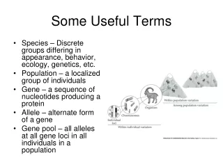
Decoders • Decoders are typically N–to–2Ndevices. • Typical examples include2–to–4 decoders, 3–to–8 decoders, and 4–to–16 decoders • Due to the prevalence of decimal arithmetic, we also have 4–to–10 decoders. These are specialized 4–to–16 decoders with 6 fewer pins. • The input is viewed as a binary code, specifying which of the outputs is selected.
The Enable Input • Again, in the above circuit one output will always be active. Suppose we want to have a decoder with no outputs active. We use an enable input, often denoted as “E”.
Multiplexers and Demultiplexers • Multiplexer – MUXAssociates One of Many Inputs to a Single Output • Demultiplexer – DEMUXAssociates One Input with One of Many Outputs • Circuit Inputs Control Outputs SignalsMultiplexer 2N N 1Demultiplexer 1 N 2N
Gate Delays • The output of a circuit element does not change instantaneously with the input, but only after a delay time during which the circuit processes the signal. • This delay interval, called “gate delay” is about 10 nanoseconds for most simple TTL circuits and about 25 nanoseconds for TTL Flip–Flops. • The simplest example is the NOT gate.
The Pulse Generator • Here is the circuit • Here is a time plot of the circuit’s behavior.
Sequential Circuits • Sequential circuits are those with memory, also called “feedback”. In this, they differfrom combinational circuits, which have no memory. • The stable output of a combinational circuit does not depend on the order in which itsinputs are changed. The stable output of a sequential circuit usually does depend on the order in which the inputs are changed. • We usually focus on clocked sequential circuits, in which the circuit changes stateat fixed times in a clock cycle. Clocked circuits are easier to design and understand. • All sequential circuits depend on a phenomenon called gate delay. This reflects the factthat the output of any logic gate (implementing a Boolean function) does not changeimmediately when the input changes, but only some time later.
The System Clock • There are a number of ways to view the system clock. In general, the view depends on the detail that we need in discussing the problem. The logical view is shown in the next figure, which illustrates some of the terms commonly used for a clock.
Latches and Flip–Flops: First Definition • We consider a latch or a flip–flop as a device that stores a single binary value. • Flip–flops and clocked latches are devices that accept input at fixed times dictated by the system clock. For this reason they are called “synchronous sequential circuits”. • Denote the present time by the symbol t. Denote the clock period by . • Rather than directly discussing the clock period, we merely say thatthe current time is t after the next clock tick the time is (t + 1) • The present state of the device is often called Q(t)The next state of the device is often called Q(t + 1)
Latches and Flip–Flops: When Triggered • Clocked latches accept input when the system clock is at logic high. Flip–flops accept input on either edge of the system clock. Here we show the rising edge.
A NOR Gate with Feedback • We consider yet another circuit that is based on gate delays. This is based on the NOR gate, which is an OR gate followed by a NOT gate. • The important thing to note is can be expressed in two equations.
A NOR Gate with Feedback (Part 2) • Consider the following circuit. When X = 1, Z = 0, and Y = 0. It is stable. Just after X becomes 0, we still have Z = 0 and Y = 0 due to gate delays. But NOR(0, 0) = 1, so after one gate delay,we have Z = 1 and Y = 1. But NOR(0, 1) = 0, so after another gate delay, we have Z = 0.
Cross–CoupledNOR Gates: The SR Latch • The two inputs to the top NOR gate are 0 and Q. Butso this part of the circuit is stable. The two inputs to the bottom NOR gate are 0 and . • This circuit is stable for S = 0 and R = 0.
The SR Latch S = 1, R = 0 (Step 1) • Let the above be in either state (Q = 0 or Q = 1) and change the external input. At first, the output does not change (remember the gate delays).
The SR Latch S = 1, R = 0 (Step 2) • After one gate delay, the output of the top NOR gate changes to 0. • This holds for any value of Q, either 0 or 1.
The SR Latch S = 1, R = 0 (Step 3) • The inputs to the bottom NOR gate are now 0 and 0. After another gate delay it changes. • This situation is stable.
The SR Latch S = 0, R = 1 • We can trace the sequence for S = 0 and R = 1. • Again, what happens does not depend on the present state, denoted by Q. • Here is the final stable state
What about S = 1 and R = 1? • Remember that if one input of a NOR gate is logic 1, its output is logic 0. Specifically for any value of Q, we have: What we have is logical nonsense. It is stable.
The SR Characteristic Table • The response of any flip-flop is described by a table called the “characteristic table”. There is another table, called the “excitation table” that is useful for digital design.
The Clocked SR Latch • Clocked latches are sometimes called “level triggered flip–flops”. This is sensitive for clock high.
The Clocked D Latch • Here is a variant of the SR latch specialized to store data. The D Latch, also called the “Data Latch”, storing data on every clock pulse.
The Feedback Problem • Clocked latches have one major problem: they are sensitive to input for too long a time. Overly extended sensitivity to input can lead to instabilities. • Consider the following problem, which is routinely addressed in a computer. There is a register called the PC (Program Counter).As a regular part of program execution it is incremented: PC (PC) + 1. • This operation is so frequently done that every CPU has a dedicated path for it.
The Feedback Problem (Part 2) If the feedback comes too soon, this adds 2.
Making an Edge-Triggered Device • We need to reduce the time during which the register will accept input. What we need is reflected in the following timing diagram.
How About the Pulse Generator • A clocked latch modified to be edge triggered is called a flip-flop.
The SR Flip-Flop (Again) • Here is the standard diagram for the SR flip–flop. • Here is the characteristic table
The D Flip-Flop (Again) • Here is the standard diagram for the D flip-flop. The characteristic table is quite simple.
Another Flip-Flop: The T • For input T = 0, this stays the same. For input T = 1, this changes state between 0 and 1.
The JK Flip-Flop as a General Device • A JK flip–flop generalizes the SR to allow for both inputs to be 1. The characteristic table