Download
1 / 1
10 likes | 125 Vues
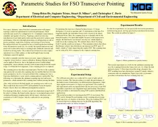
This study explores the optimization of pointing latency in free-space optical (FSO) transceivers by analyzing motor parameters such as acceleration and scanning step size. Through experimental setups and simulations, we identify the best motor characteristics that minimize latency while maintaining a robust link profile. Key factors affecting scanning time include beam divergence, receiver aperture, and lens aberrations. The findings indicate that optimal configurations significantly reduce scanning time and enhance the overall efficiency of optical wireless communications.

E N D
Parametric Studies for FSO Transceiver Pointing Latency (sec) L1 Acceleration (1000 pulse / sec2) Figure3. Experimental Setups Starting rate (1000 pulse / sec) Figure 4. Motor parameter to packet latency Figure2. Simulation Results. Figure 5. Link pattern and profiles Determine the application distance Derive θaperture Get Θ = min [θaperture, FOV] Get step size = max [θbeam, Θ] Figure 6. Best scanning step size procedure Tzung-Hsien Ho, Sugianto Trisno, Stuart D. Milner*, and Christopher C. Davis Department of Electrical and Computer Engineering, *Department of Civil and Environmental Engineering Experimental Results: For the first experiment, we can specify the best motor parameters (initial moving speed, moving speed and acceleration/ deceleration time). The results are plotted in figure 4 Simulation For pointing, the step size is limited by three factors: (1) beam divergence, (2) receiver aperture and (3) aberrations of the lens. For long link lengths, the transmitter beam can be viewed as an almost collimated beam. Thus, the scanning step size is limited only by the beam divergence. For short link lengths, because of the larger power margin, the third factor can increase our step size, which implies a reduction in the scanning time. We simulate these effects by using Code V and the results are in figure 2. This simulation shows that when the distance is short, lens aberrations can increase our FOV up to 15 mrads, which is 5 times larger than the regular FOV. The scanning time can be reduced by 96% compared to the original scanning time. Introduction: Free space, dynamic, optical wireless communications will require topology control for optimization of network performance. Such networks may need to be configured for bi- or multiple-connectedness, reliability and quality-of-service. Topology control involves the introduction of new links and/or nodes into the network to achieve such performance objectives through autonomous reconfiguration as well as precise pointing, acquisition, tracking, and steering of laser beams. Reconfiguration may be required because of link degradation resulting from obscuration or node loss. As a result, the optical transceivers may need to be re-directed to new or existing nodes within the network and tracked on moving nodes. The redirection of transceivers may require operation over a whole sphere, so that small-angle beam steering techniques cannot be applied. In order to mutually track the transceiver pairs, many techniques in computer vision (such as: camera calibration, Kalman filtering tracking) can be applied. However, due to the high-precision (2 milli-radian) requirement, vision schemes can only assist in narrowing down the search range. To obtain the best alignment, a fine scanning process is required. The scanning process has three important parts. The first is the scanning step pattern, the second is the scanning step size and the third involves the motor parameters. In [1], it was proved that if the scanning error has a Gaussian distribution, a raster spiral scanning pattern is preferable. The following is to determine the optimum scanning step size and motor parameters, which minimize the scanning time without missing the links. Also, with variation of the link length, two pointing errors will occur. They result from the receiver FOV and transmitter beam divergence. Figure 1 shows these two different misalignment scenarios. For studying both effects, we have carried out simulations using Code V. In order to evaluate the bound on the step size, we mounted transceivers on high-performance stepping motor driven stages, which provide a resolution of 0.00072 degree, which is sufficient for our pointing purposes. The second experiment is to look for the optimum scanning step size. By scanning between the transceiver sets, we obtain the link pattern in figure 5. Observing its profile along a diameter, the FOV resulting from lens aberration is around 15 mrads, which is consistent with our simulations. Figure 6 provide a systematic procedure to determine the best scanning step size. Experimental Setup: Two different procedures are conducted for a pair of agile optical wireless systems. The first procedure is to study the performance of the link in terms of data latency for different motor parameters, when large angular movements (>1 degree) are performed. The results of this experiment can be incorporated into the two processes of our PAT algorithm: acquisition (axis alignment step) and tracking. The latency in this procedure is determined by using TCP sockets with EtherPeek applications. The second procedure is to investigate the FOV of our system. The FOV can be obtained by performing a raster scanning process using small step sizes (<1 degree) of the motor. Then, the resulting FOV can be used as the best scanning step size for the PAT algorithm. The experimental results are shown in figure 3. Figure1. Two misalignment scenarios [1] M. Scheinfeild, N.S. Kopeika, and S. Arnon, “Acquisition Time Calculation and Influence of Vibrations for Microsatellite Laser Communications in Space”, Acquisition, Tracking, and Pointing XV, M.K. Masten and L.A. Stockum, Proc. SPIE4365, pp. 195-205, 2001.