Download
1 / 15
150 likes | 170 Vues
Learn how to use Autodesk Inventor 2008 to create a 3D machine part. This step-by-step tutorial covers sketching, extruding, cutting, filleting, and applying materials.

E N D
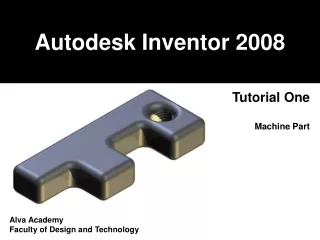
Autodesk Inventor 2008 Tutorial One Machine Part Alva Academy Faculty of Design and Technology
Use the LINE tool to draw the sketch profile shown on the next page. • Here are some useful tips to help you: The Line Tool can be found in the 2D Sketch Panel. Watch out for drawing symbols which tell you when you are sketching parallel and perpendicular! Note the dotted line used to show When you are ‘lined up’.
Start by sketching out a rough F shape. Add dimensions (press D as a shortcut) or select it from the 2D Sketch panel as shown above. Simply select a line to dimension and drag it. Double click to change the size. Press ‘HOME’ on the keyboard to view the entire sketch.
When you have completed your valid sketch profile, follow these three steps: • Right mouse click and select DONE. • Right mouse click and select FINISH SKETCH. • Right mouse click and select ISOMETRIC VIEW. • This should be completed every time that you finish a sketch.
Now that you have completed your sketch, you will notice that the 2D Sketch Panel has changed to the Part Features Panel. This allows you to complete additional tasks. Let’s make our ‘F’ shape 3D Dimensional. Select the EXTRUDE option (or press ‘E’ on the keyboard). You will notice that the extrusion will be automatically applied to our sketch. This is because we only have ONE Profile. If you have more than one sketch, you would need to select it manually.
From within the Extrude pop up window: Change the distance value to 20mm. You will notice how the projection can be altered by switching the workplane extrusion to above, below or about. Make sure that you have the solid model output mode selected.
You can rotate the 3D model by selecting the ROTATE symbol from the top icon bar. Use the mouse to select a handle and drag the model position to alter the view. DO NOT use the keyboard to manipulate the model. Rotate symbol Left mouse click and drag any of these handles. Take a few minutes to play with this tool. When you have finished, press ‘F6’ on the keyboard and return the view to it’s original isometric position.
Lets put a circular hole through our model. Select SKETCH from the icon bar at the top of the screen (or press ‘S’ on the keyboard). Choose the surface on which you want to sketch. Notice how the chosen surface boundary has been highlighted in red. If you have complex shapes, you can toggle through the surface using the selection tool as show below. Highlighted boundary Surface selection tool
So that we can clearly see what we are sketching, let’s change our view. Click the LOOK AT tool and then select the sketch surface. (Notice how the 2D Sketch Panel has came back!). You might need to press ‘HOME’ on the keyboard to view the entire surface. Take a few minutes to play with the ZOOM features. ZOOM features LOOK AT tool
Switch on the CONSTRUCTION LINE tool. Use the LINE TOOL to connect the diagonals as shown below. Deselect the CONSTRUCTION LINE tool and draw a circle on the centre of the line that you have drawn. (Notice that it is shown as a broken line). Watch out for the green dot. This indicates that you have snapped to the centre. Dimension the circle to diameter 15mm. Complete your sketch and toggle to ISOMETRIC.
Use the EXTRUDE feature to select the circle and cut through the object. You will need to change the cutting properties. Play around with it until you get the result that you want! Why not try adding more holes and extrusions to your model? You do this in exactly the same way!
We’ve almost finished! Let’s add some fillets to our model. This will make it look much smoother. Select FILLET from the 3D Sketch Features Panel (or press ‘F’ on the keyboard). You can change the size of your fillet by clicking here. Change the size to 5mm. Now select the edges that you want to round and then press OK.
Great! Let’s add the finishing touch.
Choose a material from the drop down menu as shown below. Some materials work better than others. Try a few until you find one that you like. It’s always worth remembering what the model is going to be. Choose a material that best reflects the part in real life.
You will notice that the inside of the hole appears to have a thread. This was done by selecting the inside surface, right mouse clicking and changing the properties to THREADED. You have finished this tutorial. Please save you work!