Download
1 / 15
150 likes | 372 Vues
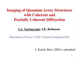
Imaging of Quantum Array Structures with Coherent and Partially Coherent Diffraction. I.A. Vartanyants , I.K. Robinson Department of Physics, UIUC, Urbana-Champaign,USA. J. Synch. Rad. (2003), submitted. X-ray scattering on nanostructures GISAXS measurements. -0.03. Q y ( Å -1 ). 0.03.

E N D
Imaging of Quantum Array Structures with Coherent and Partially Coherent Diffraction I.A. Vartanyants, I.K. Robinson Department of Physics, UIUC, Urbana-Champaign,USA J. Synch. Rad. (2003), submitted
X-ray scattering on nanostructuresGISAXS measurements -0.03 Qy (Å-1) 0.03 High-resolution AFM images of PbSe dots on PbEuTe showing the pyramidal island shape -0.03 0.03 0.0 Qx (Å-1) J.Stangl et al. Material Science & Engineering, C19 (2002) 349
Imaging of Quantum Dots with Coherent Beams Source Sample CCD Electron density of periodical array of QD’s S(r) – shape of coherently illuminated area sz(r) –projection of shape of one island s(r,z) Scattered amplitude Diffracted intensity cross terms
2D array of QD’s and it’s diffraction pattern 2D array of QD’s Diffraction pattern of 2D array Image of individual island Diffraction pattern of individual island
Reconstructed image of 2D array of QD’s Support used for reconstruction Diffraction intensity of reconstructed image Reconstructed image with superposition of twin images Reconstructed image
Imaging of QD’s with partially coherent beams Intensity distribution with partially coherent illumination p(r) - electron density distribution, Jin(r) - mutual intensity function lcoh – transverse coherence length Complex coherence factor Intensity distribution Diffracted intensity from 2D array of QD’s: cross terms
Tests of Partial Coherence Effects in Imaging 2D array used for tests of partial coherence effects Diffraction pattern of 2D array Shape of individual island Diffraction pattern of individual island A. Szöke Acta Cryst. (2001) A57, 586
Diffraction intensity from QD’s with partial coherent illumination lcoh= lcoh= 124 px lcoh= 64 px lcoh= 31 px Complex Coherence Factor in(r) Diffraction intensity distribution
Iterative phase retrieval algorithm FFT sk(x) Ak(q) Real Space Constraints Reciprocal Space Constraints s'k(x) A'k(q) FFT-1 • Real space constraints: • finite support • real, positive Reciprocal space constraint: R.W.Gerchberg & W.O. Saxton, Optic (1972) 35, 237 J.R. Fienup, Appl Opt. (1982). 21, 2758 R.P. Millane & W.J. Stroud, J. Opt. Soc. Am. (1997) A14, 568
Reconstructed images with reduced coherence Reconstructed image of the whole array Reconstructed image of central island
Ge islands on prepatterned Si substrates AFM micrographs of 1D (a) and 2D ordered Ge islands (b) with corresponding line scans Zhenyang Zhong, A. Halilovic, F. Schäffler, G. Bauer Institut für Halbleiter-und Festkörperphysik, Johannes Kepler Universität Linz
Diffraction pattern around Ge (202) peak 1.95 Qz 1.89 Qx 2.025 1.965 Experiment on ID34 APS (June 2003)
Diffraction pattern from Ge islands GISAXS measurements i c f Qy Qy i> c i< c
Conclusions • Diffraction pattern from 2D array of QD’s can be inverted to give the correct shape and orientation of individual island • For successful reconstruction experimental diffraction pattern has to be measured up to Q~2/a (a - average size of an island) • Test calculations for very small transverse coherence lengths lcoh of the incoming beam were made • Correct shape of the individual island can be obtained when lcoh~a