Air
Air Separation. Air. Sher Shah . Amarkhail Supervisor . Dr. Juma Haydary. SAMRS 2009/09/02. Kabul Polytechnic University , Faculty 0f Chemical technology 10.11.2010 Institute of Chemical and Environmental Engineering, Slovak University of Technology in Bratislava,

Air
E N D
Presentation Transcript
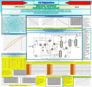
Air Separation Air Sher Shah . Amarkhail Supervisor . Dr. JumaHaydary SAMRS 2009/09/02 Kabul Polytechnic University , Faculty 0f Chemical technology 10.11.2010 Institute of Chemical and Environmental Engineering, Slovak University of Technology in Bratislava, Radlin ského 9, 812 37 Bratislava, Slovak Republic INTRODUCTION Air at lower temperatures (-196oC) becomes in liquid and so can do the distillation of air to its components. Distillation of air is currently the most commonly used technique for production of air component, in industrial scale. Air separation plants are designed to generate oxygen, nitrogen and pure argon from air through the process of compression, cooling, liquefaction and distillation of air. As an experienced and knowledgeable manufacturer of air separation plants with the most advanced technology. Air also using for production of oxygen gas, nitrogen gas, squeezed air, dry air for control and automatisation of devices. The current work aims to describe the air separation process including heat exchange and cryogenic distillation. An ASPEN Plus simulation of cryogenic air separation into Nitrogen, Oxygen and Argon is created. The influence of different process parameters on distillation efficiency is analyzed. Thermodynamic of air separation Using the Peng- Robinson equation of state the isobaric t, xy and x,y diagrams of N2-O2 and Ar-O2 binary systems at different pressures were calculated: P = 1 .4 at at 1.4 atmosphere: Figure 1 :T,X,Y- diagram,N2 – OFigure 2 :X,Y diagram,N2- O2 Figure 3 : T,X,Y- diagram, Ar- O2 Figure 4 : X,Y- diagram, Ar – O2 Aspen simulation of air separation process Technical specifications of KT – 1000 M plant: Volume flow of the air m3/hr: High pressure air 800 m3/hr at pressure 160at 5321.4 kmol/hr Low pressure air 3500 m3/hr at pressure 5at 727.5 kmol/hr Volume of producted oxygen 1243.877 kmol/hr Volume of producted nitrogen 4760.309 kmol/hr Volume of producted Argon 44.714 kmol/hr Mol fraction of oxygen 98.7% Mol fraction of nitrogen 99.0% Mol fraction of Argon 99.9 % Air separation technology scheme Calculation of air distillation by McCabe-Thiele method Figure 5: X-Y diagram, vapor and liquid N2 Capital investment costs of air distillation Table 8: calculation of investment costs Figure 6: scheme of the air separation C1,C2,C3 are column 2 – S1,S2,S3,S4,S5,B8,B10 are mixers 3-HEO2,HEM2,HE1,HE2,HE3,HE4 are heat exchangers 4 – Expander Figure 37: Number of theoretical stages versus Reflux ration in column C3 for, Argon purity: 0.99, Argon recovery:0.999 Table 1:results of study state simulation of air distillation process Composition profile C3 This diagram shows the composition of oxygen , nitrogen and Argon in different stage number of column 3. Figure 6: Composition profile of column C3 Temperature profile C3 This diagram shows the temperature in different stage of column C3. It shows the temperature will be higher up from lower to the bottom of column3 Figure 7:Temperature profile of column C3 Optimization of distillation columns parameters
Air separation technology scheme Scheme of the air separation process C1,C2,C3 are column 2 – S1,S2,S3,S4,S5,B8,B10 are mixers 3-HEO2,HEM2,HE1,HE2,HE3,HE4 are heat exchangers 4 – Expander, B1, B2 are compressors, B3 and B4 coolers of compressors