Download
1 / 1
10 likes | 135 Vues
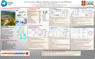
An Assessment on Klystron Modulator Topologies for the ESS Project Carlos A. Martins (*), Karin Rathsman(**) (*) – Laval University, Dept. Electrical and Computers Engineering, Québec, QC, Canada (**) – European Spallation Source, Accelerator Division, Lund, Sweden.

E N D
An Assessment on Klystron Modulator Topologies for the ESS Project Carlos A. Martins (*), Karin Rathsman(**) (*) – Laval University, Dept. Electrical and Computers Engineering, Québec, QC, Canada (**) – European Spallation Source, Accelerator Division, Lund, Sweden 1. - The European Spallation Source Project 3. - Main Parameters of ESS Klystron Modulators b) – Direct Switch d) – Interleaved Multi –level Converters V Rise time Fall time time Flat-top • Key issues: • Arcingenergy; • Reverse voltage; • Droop (lowfreq. oscillations); • Ripple on flat-top; • Safetyconcerns (oil; cap. dischargesystems) Pulse width • Principle • A 3-phase transformer, with multiple (N) secondary winding systems, feeds N isolated capacitor chargers; • DC/DC converters are supplied by the capacitor banks and generate a variable DC voltage at their outputs, however with high HF contents; • The output of all the DC/DC converters are connected in series for voltage multiplication; • A common passive filter extracts the HF contents; • Advantages • Active demagnetisation of the pulse transformer possible with additional switchnig devices (in red); • Active droop compensation system within closed loop feedback; • Partially modular system; • Hard points / limitations • Flat-top voltage ripple may be high (depending on interleaving techniques adopted and dissemetries between modules); • Thermal management of semiconductors. Impact on reliability? • Two special transformers are required (3-phase multisecondary-winding & HV pulse transformer) • Principle • A capacitor bank is charged directly at the klystron voltage level by a HV power supply; • The HV capacitor bank is applied directly to the klystron by using a HV switch; • The HV switch, formed by a series connection of medium-voltage IGBT’s, stops the pulse in normal operation and in case of arcing; • A fast switch mode power supply compensates for the droop in closed loop. • Advantages • - Very fast rise/fall times are possible; • - Easily adaptable to a very large range of pulse length and pulse repetition rate requirements; • - Compact solution; • Hard points / limitations • - All power components are in oil (longer time access for repair, large quantities of oil required); • - Reliability in arc protection is dependent on the reliability of the HV switch; • - Effectiveness of droop compensation system to be proven in large average power and repetition rate applications; • - High voltage (up-to ~100kV) IGBT assembly technology is single source and patented. Energy Sustainability for Large Research Facilities (RRR – Responsible, Renewable, Recycle) 4. - Solid State Klystron Modulator Topologies (long pulses) • Some Key Figures: • European Spallation Source ESS AB • 17 partner countries including Sweden and Denmark; • Pre construction Phase started in 2009 and ends in February 2013; • Next phase is the Construction Phase; • European Spallation Source will open in 2019 and become fully operational in 2025; • Total cost: 1.48 Billion €. e) – Multi-Level Resonant Converters c) – Marx generator a) - Pulse Transformer based • Principle • Medium voltage capacitor bank is charged through a capacitor charger and discharged by using a HV solid state switch on a pulse transformer (PT); • The PT rises the voltage up-to the level required by the klystron; • A passive LC resonant bouncer system compensates for the voltage droop; • A damping circuit is used to demagnetize the transformer at the end of each pulse. • Advantages • Simple, Reliable; • All electronic active devices are at a medium-voltage level (transformer primary side); • In case of arc, the dI/dt is limited by the leakage inductance of the pulse transformer, which gives time to open the solid state switch (may be rather slow, ~10 µs switch off-time) ; • Absence of high-frequency voltage ripple on the flat-top; • Hard points / limitations • Construction of the pulse transformer (single source: Stangenes); • Very large and costly pulse transformers for high average power applications; • Bulky and costly LC resonant bouncer for high average power applications, with poor performance (open loop compensation system); • Availability of medium voltage solid state switches (few sources: ABB, Dynex, ...); • Reverse voltage on the klystron to demagnetize the pulse transformer may be a limitation to the duty cycle; • Principle • N capacitor banks are charged in parallel from a medium voltage charger, -HV (~ -10 kV); • All capacitor banks are connected in series during the discharge (pulse forming), therefore output voltage = N x VC;(N: number of marx cells, VC: Voltage across each capacitor) • At each cell, DC/DC converters are used to power the driver electronics (mini-marx generator); • Advantages • - Very fast rise/fall times are possible; • Compact; • Oil free (no oil maintenance, security issues); • Very high efficiency (>95%); • Modular design with easy access to components for repair; • Hard points / limitations • - Air insulation may have a strong impact on long term reliability, which is affected by air conditions; • - Fast electric fields constitute a major concern in the reliability of sensitive electronic components used in the IGBT drivers. Requires advanced modelling and shielding techniques to tackle the problem; • - Reliability of the solid state switches; • - Reliability in protecting the klystron in case of arcing (all switches must open simultaneously to guarantee safe protection of the klystron); • - The droop compensation technique (fast PWM regulators & late firing of cells) may not be acceptable in many applications, since the residual HF voltage ripple in the flat-top is high. • Principle • N H-bridges are fed from a common DC-link bus. Each H-Bridge supplies a circuit formed by:- a LC series resonant circuit, a HF step-up transformer, a diode rectification bridge and a HF filter; • The output of the different circuits are connected in series:- the total output voltage is multiplied by N; • Several capacitor chargers and capacitor banks may be used in parallel to improve modularity; • Advantages • All active electronic components are at the transformer primary side (medium voltage level); • Semiconductor switches and drivers are of standard commercial types (multisource); • HF transformers operate in AC mode. No intrinsic limitations exist on the pulse length; • Flat-top voltage (droop) is regulated in closed loop; • Intrinsic voltage shut-down in case of klystron arcing (De-Qing); • Modular topology (4 or 5 independent modules in parallel/series); • Hard points / limitations • Construction of the HF transformers (mechanical stress due to pulsed operation, High Frequency (20 kHz) design with High Voltage insulation (120 kV at highest point) and high average power (tens kW); • H-bridges shall handle a significant amount of reactive power and must be therefore oversized; • Long rise times (several tens µs) are required; • Assure “soft-switching” of the IGBT’s in all operating points. Safe interlocking if soft switching is not met; • Mitigation of HF ripple on the flat-top (control accuracy, symmetry between modules); • Thermal management of semiconductors. Impact on reliability?; 2. – The ESS Superconducting Linac • Key parameters • A proton linac; • Proton energy range: 1 to 2.5 GeV; • Pulse frequency range: 10 to 20 Hz; • Pulse length range: 0.8 to 3.5 msec; • Beam power nominal: 5 MW; • Beam on target: > 95 % reliability; • Beam loss: ~ 1 W/m. 5. - Assessment of topologies under the ESS framework • Marx generator :- it’s not proven yet on an industrial scale for the level of voltage and power required by ESS; • Multilevel Resonant converter (similar to the SNS topology):- requires further investigation and practical validation; however, it would be an extremely interesting solution (all standard components, modularity, D-Qwing, compactness, flat-top precision); • Pulse Transformer based:- it’s reliable and HF ripple free; volume and cost may be limiting factors due to the large pulse transformer and passive bouncer required; PT demagnetization may be an issue; • Direct Switch:- reliability and availability of HV switch assemblies must be proven; large quantities of oil required; accessibility for repair and diagnosis is limited; • Interleaved multilevel converter:- reliability must be proven; cost and volume may be limiting factors due to the presence of two special transformers;