Toshiba Klystron for Ultrafast Electron Diffraction: Final Design Review
280 likes | 363 Vues
This presentation covers the final design review of a high-power klystron modulator system for ultrafast electron diffraction, detailing system overview, matching, operation points, interlocks, and responses to design review feedback.

Toshiba Klystron for Ultrafast Electron Diffraction: Final Design Review
E N D
Presentation Transcript
SDL Ultrafast Electron Diffraction Klystron Modulator Feng Gao, Michael Fulkerson, Gloria Ramirez, Xijie Wang Presented at the UED Modulator Final Design Review November 5, 2010
Outline • Introduction • Highlights • Response to the Intermediate Design Review Report • UED modulator checklist • PLC and hardware for Fil/Sol/HV protection • Interlock check record • Summary and path forward.
Why Toshiba klystron? — The SDL ultrafast-electron-diffraction (UED) beamline needs 5MW of RF power with a repetition rate of 10Hz, to reach a temporal resolution of ~100fs. — A solution for the NSLS spare: 20MW up to 2Hz.
UED Klystron System Overview Klystron Remote computer control Klystron Ion pump supply PLC Controller Solenoid Magnet Solenoid Power Supply Water Air HV Crash HV door Smoke Det Vacuum Arc Det Trigger Vac Intlk Trigger Interrupt Thyratron Filament Thyratron Trigger Pulse Xfmr Thyratron Switch PFN Modulator HV Supply Filament Supply
NSLS XK5 tank + Toshiba klystron extension piece Perveance = 2.08μperv
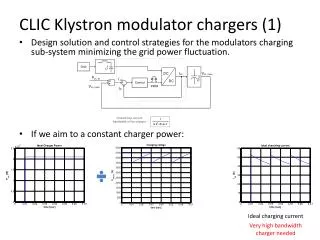
The PFN Based on the NSLS PFN parameters for each section: Capacitance = 0.04uF, rated 50kV; Inductance = 1.69uH (needs tuning). The PFN pulse length = (0.04uF*1.67uH)^.5 * 10 sections * 2 = 5.2us The PFN impedance = (1.67uH/0.04uF)^.5 = 6.46 Ohm The thyratron is rated as 45kV. Dummy load for testing purpose: 10/2 = 5 Ohm, rated 75kV
Matching between PFN and klystron The klystron tank has a HV transformer with a ration of 1:12, and the klystron HV is limited by the thyratron rating (45kV). If the PFN and klystron are well matched, the klystron HV can only go to: 45*12/2 = 270kV. Since we do not need 51MW full power, it would be good to keep the klystron operate at 80% of the nominal HV: 312kV*80% ~ 250kV < 270kV. Assume the perveance is still 2.08μperv , the cathode current would be: 250kV^1.5*2.08μperv = 260A ; and the impedance of the klystron tube would be 250kV/260A = 962 Ohm. This impedance converted to the PFN side would be: 962 Ohm / 12^2 = 962/144 = 6.68 Ohm, which is close to the PFN impedance 6.46 Ohm. Well matched. The available power from the klystron would be: 250kV*260A*40%(est.) = 26MW > 20MW needed for NSLS.
Operation point of the klystron filament — The power to the filament transformer is cut off if filament current > 20A; — Secondary protection: a circuit breaker at the primary of the transformer. Tentative, needs heater curve test.
Interlock: shut down power supplies externally External contactor box controls power to the following: — 120AC power strip except for the PLC power. Can turn off klystron filament / core bias supplies, thyratron heater / reservoir supplies; — 208AC power to the solenoid supply; — 208AC power to the HV power supply. ********************************************Each power supply also has its own front panel switch to override remote with local shut-down. E-stop shut-down overrides everything.
Solenoid protection The solenoid is protected by the following: • Two thermocouples for temperature interlock via plc software; • One 125F klixon and one 150F klixon for temperature interlock via both hardware and plc software ; • One proteous for waterflow interlock via both hardware and plc software. Low level drive A 1kW TWT amplifier has been tested and will be used to drive the klystron.
Response to Intermediate Design Review Report 1/4 (black is the original report and blue is our response) Issues discussed that are open: It was noted that UED has no existing arc detection system such as kly A, B, & C have. The new arc detection system will be needed for operation of UED (Pete Z). (Will be implemented after the modulator testing) An ESH issue was noted that since UED is not inside the envelope of the SDL control system, UED will have to be shutdown separately under its own procedure (XJ Wang). ( ES&H Check list for modulator testing, full check list after the modulator testing) The solenoid thermocouple (TC) uses standard cable from the solenoid connector and should use TC cable up to the metering point in order to get accurate data (Pete Z). (Cable changed) Time will be needed to calibrate the arc detector against the high voltage (Pete Z.). (Will be implemented after the modulator testing) An independent external watchdog timer was recommended (Gloria). (Being implemented)
Response to Intermediate Design Review Report 2/4 The use of a filament power supply soft start is recommended. This is being ordered for NSLS and should be put on the UED system. It was decided that we can install it at a later date. Testing can commence without this (Pete Z). Currently only klystron and waveguide vacuum are monitored. It was recommended that we also look at gun vacuum (Gloria). (Interlock available in PLC) It is recommended that the system have a reach-back to drop the power at the ac line for power supplies that show an ON status after being commanded OFF (Pete Z) (Not implemented since E-stop button will always be pushed in when mod not in use.) The filament time-out circuit is an external mechanical device. It was recommended that we implement this function in the PLC as well and monitor filament current and voltage as part of this function (Gloria). (Done) We must disable 2 of the 3 methods for turning on the solenoid power supply (Pete Z). (208AC to SOL supply is controlled externally, so only one way to turn it on). We will test if the interlock system can disable the next pulse, however, the response through PLC controls can be as high as 200ms (Mike F). (To be checked in modulator testing)
Response to Intermediate Design Review Report 3/4 A DAC will be needed to interface to the SDL EPICS control system (Gloria). (In place, will be used later) Things not yet completed in the PLC Controls: • PLC as of previous review: • DAC Controls (In place, will be used later) • Computer interface for ON/OFF/reset (Done) • Computer interface for Status monitoring (Done) • Interlock testing (Done) • Readback calibrations (Done) • Hardware • Proteus wiring (Done) • HV Supply readback wiring (In process) • Vacuum Interlock (In place) • Point to point wiring check (Done) Suggested changes in the PLC Controls: • Add watch-dog relay for PLC failure (Being implemented) • Add software timeout in PLC, triggered as a function of Filament current or voltage (Done)
Response to Intermediate Design Review Report 4/4 • Add remote control for Filament, Core bias and Thryratron supplies (Done) • Add Solenoid on/off logic to PLC to provide control signal to supply contactor (Done) • Interrupt the control signal to the Solenoid contactor with redundant hardware interlocks (Done) • Add calibration function to provide calibrated readbacks of voltages, currents and vacuum levels (Done) • Require ON command after fault reset (Done) • Add Status readback to remote computer (Done) • Add sequence logic for complete automated turn on (To be determined) • Change variable names to more clearly identify functions (Done)
Checklist 1/4(black is the original list and blue is my comments) From: “SDL UED klystron and modulator: the major steps and parameters for operation, Feng Gao, June 10, 2010” I. Radiation Interlock and AC power control • All AC power to the UED modulator should be able controlled either by a crash button or control panel of the control computer. The modulator AC power should stay off when crash button is activated until the crash button is reset and the AC is again commanded ON (Checked); • The UED modulator high voltage charging power will be part of the SDL radiological interlock system. We have obtained approval from the NSLS ES&H group that we can perform the UED klystron and modulator testing with the klystron output directly connected to a load. (With approval);
Checklist 2/4 II. Klystron modulator interlock and parameter control • Water flow rate in the solenoid magnet (>2.5 G/m) and klystron body and collector (> 1.0 G/min) for the 10 Hz and 25 MW operation limit (in klystron testing: 2 Hz and 25MW; in UED operation: 10Hz and 5MW ); 2.5G/min is for 40A, we are using 27.6A with 2.2G/min. Should be enough. • Solenoid magnet current (25 < I < 29 A); Set as 26.6< I <28.6A. 3. Klystron filament warm-up time (60 minutes); Both hardware and software timeout. • Filament heater voltage (<90 V (primary) = <18V (secondary), Filament heat operating point 16V and 16 A); Interlock in place, final values to be determined. 5. Klystron vacuum (< 10 uA); Now at 3uA, will be increased in conditioning. 6. Waveguide vacuum (<10-6 Torr or 30 uA); To be determined in conditioning. 7. Solenoid magnet temperature monitor (<100 F); Now at 80F, will be increased in conditioning. 8. Modulator arc detector. Will be implemented later by Peter Zuhoski.
Checklist 3/4 III. Installation checklist • Wiring check: charging HV, filament heater, core bias, thyratron, solenoid and its thermocouples, etc; Checked • Make sure solenoid magnet can be turned on only by the PLC control program, and PLC program off will automatically turn off the power supply. Watchdog being implemented. Water off and over temperature should also lead to the solenoid magnet power supply off both through the plc logic and hardwired in series with contactor; Checked • Grounding connection: modulator, klystron, solenoid magnet and klystron tank must be grounded together explicitly; Solenoid will be connected to the supply and then grounding connection will be checked. • Water system: solenoid magnet and klystron collector and body; Checked. • Shielding: lead shielding around klystron should be carefully assembled based on the Toshiba instructions. Checked.
Checklist 4/4 IV. Check list prior operation • Tank inspection; Done. • Tank HV divider calibration checked and labeled; Done • Klystron cathode current calibration checked and labeled; Done. • Filament voltage check; Done –Final operating setting TBD. • Thyratron operating parameters; Done. • Filament heater (16Vx16A); Done –Final operating setting TBD. • Filament warm up time (60 minutes); Done. • Solenoid magnet flow rate and current (2.5 G/min and 27.5A); Done. • Vacuum readings for klystron and waveguide. TBD. V. Fault testing A fault testing will be done for all critical parameters listed in section II plus AC power turn on/off functions. See results on later slide. VI. UED klystron testing A waveguide load should be connected to the UED klystron output with a calibrated directional coupler. The maximum output for this testing should not exceed 25 MW (UED only needs maximum 10 MW). Load in place. Power will be controlled by a variable attenuator at low level.
Klystron Filament Current Monitor FOCUS SUPPLY AC Control - PLC
HV SUPPLY AC Control - PLC
HV ON/OFF Control Hardware
Summary • All Issues raised in the intermediate review are addressed. • Comprehensive check list developed. • Critical interlocks pass the test. • Radiation, magnetic field and RF survey will be done during the turn on of the modulator. We are ready for the Modulator and Klystron Testing.
Path forward • Test the PFN with the 5 Ohm dummy load; • Send HV to the klystron tank, use initial I_fil = 15A and v_fil = 16V to condition the tube up to ~250kV, without RF; • Tune the PFN as needed; • Heater curve test; • RF conditioning and klystron power check. We thank Ken Pedersen for his assistance with wiring checks, documentation and drawings for the presentation, and thank all the people who have helped on this modulator construction. Thank you!