Microprocessor Design
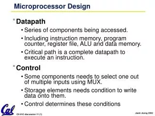
Microprocessor Design. Datapath Series of components being accessed. Including instruction memory, program counter, register file, ALU and data memory. Critical path is a complete datapath to execute an instruction. Control

Microprocessor Design
E N D
Presentation Transcript
Microprocessor Design • Datapath • Series of components being accessed. • Including instruction memory, program counter, register file, ALU and data memory. • Critical path is a complete datapath to execute an instruction. • Control • Some components needs to select one out of multiple inputs using MUX. • Storage elements needs condition to write data onto them. • Control determines these conditions
Instruction Execution Steps: (ADD,SUB,ORI) • Let us identify the instruction execution steps in single cycle processor. • Instruction Fetch • Read instruction memory at PC and increment PC by 4. • Instruction Decode/Register Read • Read register file using the fields in the instruction • Execution • Do the ALU operation • Memory • Load data from the memory or store data into the memory • Write Back • Write any data back to the register file if we have anything to write
Instruction Execution Steps: (ADD,SUB,ORI) • ADD, SUB, OR • IF: Load instruction and increment PC by 4 • ID: Read two regs (ADD/SUB) Read one reg and zero extend immediate (ORI) • EX: Do arithmetic in ALU • Mem: Do nothing • WB: Write the result of ALU into reg file. • BRANCH (beq): • IF: Load instruction • ID: Read two registers (rs, rt) • EX: Calculate the difference of rs and rt in ALUIf ALUout = 0 PC <- PC + 4 + (signext(imm)||00) ALUout != 0 PC <- PC + 4 • Mem: Do nothing • WB: Do nothing
Instruction Execution Steps: LOAD/STORE • LOAD Word • IF: Load instruction and increment PC by 4 • ID: Read one reg (rs) and sign extend immediate • EX: Calculate memory address in ALU • Mem: Read a word from memory with the address • WB: Write the result of ALU into reg file (rt) • STORE Word • IF: Load instruction and increment PC by 4 • ID: Read one reg (rs) and sign extend immediate • EX: Calculate memory address in ALU • Mem: Write register rt into the memory • WB: Do nothing
Instruction Execution Steps: branch • BRANCH (beq): • IF: Load instruction • ID: Read two registers (rs, rt) • EX: Calculate the difference of rs and rt in ALUIf ALUout = 0 PC <- PC + 4 + (signext(imm)||00) ALUout != 0 PC <- PC + 4 • Mem: Do nothing • WB: Do nothing
Inst Memory Adr Adder Mux Adder Putting it All Together:A Single Cycle Datapath Instruction<31:0> <0:15> <21:25> <16:20> <11:15> Rs Rt Rd Imm16 RegDst nPC_sel ALUctr MemWr MemtoReg Equal Rt Rd 0 1 Rs Rt 4 RegWr 5 5 5 busA Rw Ra Rb = 00 busW 32 32 32-bit Registers ALU 0 32 busB 32 0 PC 32 Mux Mux Clk 32 WrEn Adr 1 1 Data In Data Memory imm16 Extender 32 PC Ext Clk 16 Clk imm16 ExtOp ALUSrc
PC ALU Clk Review: An Abstract View of the Critical Path Critical Path (Load Operation) = Delay clock through PC (FFs) + Instruction Memory’s Access Time + Register File’s Access Time + ALU to Perform a 32-bit Add + Data Memory Access Time + Stable Time for Register File Write • This affects how much you can overclock your PC! Ideal Instruction Memory Instruction Rd Rs Rt Imm 5 5 5 16 Instruction Address A Data Address 32 Rw Ra Rb 32 Ideal Data Memory 32 32 32-bit Registers Next Address Data In B Clk Clk 32
Quiz • Given the following information, please calculate the cycle time of the single cycle CPU: • Instruction memory access time: 1 time unit • Instruction decoding time plus register read time: 1 time unit • ALU operation time: 0.9 unit • PC update time: 0.1 unit • Data memory access time: 1 time unit • Register file update time: 1 time unit From Li Yin’s note
Draw the data path • Now we understand what each instruction does, we can draw the datapath for each instruction.
Inst Memory Adr Adder Adder Draw the data path: ADD or SUB Instruction<31:0> <0:15> <21:25> <16:20> <11:15> Rs Rt Rd Imm16 Rs Rt 4 5 5 5 Rw Ra Rb = 00 32 32-bit Registers ALU PC Clk WrEn Adr Data Memory Extender PC Ext Clk Clk
Inst Memory Adr Adder Adder Draw the data path: ORI Instruction<31:0> <0:15> <21:25> <16:20> <11:15> Rs Rt Rd Imm16 Rs Rt 4 5 5 5 Rw Ra Rb = 00 32 32-bit Registers ALU PC Clk WrEn Adr Data Memory Extender PC Ext Clk Clk
Inst Memory Adr Adder Adder Draw the data path: Load word Instruction<31:0> <0:15> <21:25> <16:20> <11:15> Rs Rt Rd Imm16 Rs Rt 4 5 5 5 Rw Ra Rb = 00 32 32-bit Registers ALU PC Clk WrEn Adr Data Memory Extender PC Ext Clk Clk
Inst Memory Adr Adder Adder Draw the data path: Store word Instruction<31:0> <0:15> <21:25> <16:20> <11:15> Rs Rt Rd Imm16 Rs Rt 4 5 5 5 Rw Ra Rb = 00 32 32-bit Registers ALU PC Clk WrEn Adr Data Memory Extender PC Ext Clk Clk
Inst Memory Adr Adder Adder Draw the data path: Branch equal Instruction<31:0> <0:15> <21:25> <16:20> <11:15> Rs Rt Rd Imm16 Rs Rt 4 5 5 5 Rw Ra Rb = 00 32 32-bit Registers ALU PC Clk WrEn Adr Data Memory Extender PC Ext Clk Clk
nPC_MUX_sel Inst Memory Adr 4 Adder 00 Mux PC Adder Clk imm16 PC Ext Meaning of the Control Signals • To understand control, we need to know when each of signals is turned on. • nPC_MUX_sel: 0 PC <– PC + 4 1 PC <– PC + 4 + {SignExt(Im16) , 00 }
Meaning of the Control Signals • MemWr: 1 write memory • MemtoReg: 0 ALU; 1 Mem • RegDst: 0 “rt”; 1 “rd” • RegWr: 1 write register • ExtOp: “zero”, “sign” • ALUsrc: 0 regB; 1 immed • ALUctr: “add”, “sub”, “or” RegDst ALUctr MemWr MemtoReg Equal Rt Rd 0 1 Rs Rt RegWr 5 5 5 busA = Rw Ra Rb busW 32 32 32-bit Registers ALU 0 32 busB 32 0 32 Mux Mux Clk 32 WrEn Adr 1 1 Data In Data Memory imm16 Extender 32 16 Clk ExtOp ALUSrc
31 26 21 16 11 6 0 op rs rt rd shamt funct immediate op rs rt A Summary of the Control Signals See func 10 0000 10 0010 We Don’t Care :-) Appendix A op 00 0000 00 0000 00 1101 10 0011 10 1011 00 0100 add sub ori lw sw beq RegDst 1 1 0 0 x x ALUSrc 0 0 1 1 1 0 MemtoReg RegWrite 1 1 1 1 0 0 MemWrite 0 0 0 0 1 0 nPCsel OR: 001 ExtOp x x 0 1 1 x ADD: 010 ALUctr<2:0> Add Subtract Or Add Add SUB: 110 Subtract 0 1 0 0 0 1 ALUctr<2> 1 ALUctr<1> 0 ALUctr<0> R-type add, sub I-type ori, lw, sw, beq
Writing controls in Boolean formula • Express following variables in Boolean formula ofOPCode and Func • Add = OP[5]*OP[4]*OP[3]*OP[2]*OP[1]*OP[0] *F[5] *F[4] *F[3] *F[2] *F[1] *F[0] • Sub = • Ori = • Lw = • Sw = • Beq =
Writing controls in Boolean formula • Express following variables in Boolean formula ofAdd, Sub, Ori, Lw, Sw, Beq, OPCode, or Func • RegDst = Add + Sub • ALUSrc = • MemtoReg = • RegWrite = • MemWrite = • nPCsel = • ExtOp = • ALUctr<2>= Sub + Beq • ALUctr<1>= • ALUctr<0>=