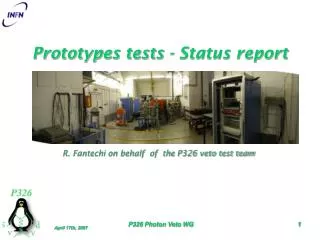
Report on mirror support tests
Latest updates include mirrors' optical surface finishing, cutting of mirrors to hexagonal shape, aluminization, and coating outlook at CERN. Tests with single dowel and leaf springs prototypes are detailed. Results show stable movements and mirror positions.


Report on mirror support tests
E N D
Presentation Transcript
Report on mirrorsupporttests M.Lenti
Latest news fromMarcon • Mirrorsopticalsurfacesfinished • Since last week start cutting (fromcirculartohexagonalshape) with water jet tool • Aftercutting: re-checkingofopticalsurfaces • Shippingofall the mirrors at CERN foreseenby the end of the year • At CERN: aluminization and coating
Outlook • Testswith “single dowel” prototype • Testswith “leafsprings” prototype (doubledowels) • Useanaluminummock-up in placeof a truemirror (samedimensions and weight) • Smallmirrorfixed on the aluminumhexagonfor laser beamreflection • Position sensitive photodiodeused (x,y)
Single dowel • Full prototyperealized • “single dowel”: mirrorhung at the center • Mirrormovementaround u and v axis (insteadof x and y) • pulled at ±45 degrees (axisdecoupling) • Mirrorweight: counterbalanceforbothmovements • Piezo-motor (final) used • 0.25 mm thickaluminiumribbon (directtraction, no 90 degdeviation), 13 mm wide piezo piezo dowel dowel piezo dowel
Single Dowel Controller mirror Piezo Motor Laser 2 1 PhotoDiode 0.25 mm thickribbon Piezo Motor
PiezoMotors controller
A, B ribbon joint on the mirror O doweltouchingpoint G mirrorbarycenter P, Q piezo-motor kinematics A B A l l O O P Q G P G y y z x z x
Single dowel: try a closedloop Starting point End point Spot position on the PhotoDiode P1: piezo n.1 P2: piezo n.2 F: forward R: backward Laser-mirrordistance: 60 cm Mirror-photodiodedist: 90 cm P2R P1F 100 μm Fromonepointto the next: 100 microstep movementsof the Piezo (31.25 μm) 100 μm on the phtdiode → 70 μrad on the mirror P1R P2F y 100 μm x
Single Dowel: forward and backward Spot position on the PhotoDiode Piezo n.1 y 100 μm x time
Single Dowel: forward and backward Spot position on the PhotoDiode Piezo n.2 y Different scale w.r.t.previous slide 100 μm x time
Single dowel: stability • Dayone, time: 15:20 PM. x=+0.0335, y=+0.0329 (photodiode) • Daytwo, time: 9:00 AM. x=+0.0374, y=+0.0327 (photodiode)
Leaf Springs piezo • Full prototyperealized • “leafsprings”: mirrorhungthroughtwoholes • Mirrormovementaroundx and y axis • pulled at 0 and 90 degrees • Mirrorweight: counterbalanceforverticalmovement • Leafsprings: counterbalanceforhorizontalmovement • Piezo-motor (final) used • 0.25 mm thickaluminiumribbon (directtraction, no 90 degdeviation); l=250mm piezo dowel dowel dowels Leafsprings piezo dowel
dowels LeafSprings prototype 0.5 mm aluminiumfoils
LeafSpringprototype mirror ribbon Laser PhotoDiode Leaf Springs 0.25 mm thickribbon Piezo Motor
LeafSpring: try a closedloop End point Spot position on the PhotoDiode PV: piezo “vertical” PH: piezo “horizontal” F: forward R: backward PHR Starting point PVR Laser-mirrordist. 40 cm Mirror-phtdiodedist: 70 cm PVF 100 μm Fromonepointto the next: 100 microstep movementsof the Piezo (31.25 μm) PHF 100 μm on phtdiode → 90 μrad on mirror 100 μm y x
LeafSpring: forward and backward Spot position on the PhotoDiode PiezoHorizontal y 100 μm x time
LeafSpring: forward and backward Spot position on the PhotoDiode Piezo Vertical y 100 μm x time
LeafSpring: stability • Dayone, time: 16:20 PM. x=+0.0000, y=+0.0004 (photodiode) • Daytwo, time: 12:40 AM. x=-0.0031, y=+0.0040 (photodiode)
Conclusions • Bothapproaches (single dowel and leafspring) prototyped • New piezomotorsused (neverstucked, “small” differencesin fw and bwmovements) • Needforencoders? • In preparation: ribbonwith 90 degreedeviation (care on cutting…) • In preparation: test withglassresistance