Download
1 / 11
110 likes | 222 Vues
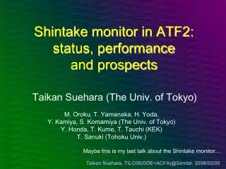
Progress of Shintake Monitor (IP-BSM) Work. KEK site meeting 2009/6/17 T. Yamanaka. Damage Threshold of Mirrors. Comparison of laser output and damage threshold of optical coating. assume Gaussian profile for space and time. FWHM=3.5 mm. Damage Threshold of Mirrors.

E N D
Progress of Shintake Monitor (IP-BSM) Work KEK site meeting 2009/6/17 T. Yamanaka
Damage Threshold of Mirrors Comparison of laser output and damage threshold of optical coating assume Gaussian profile for space and time FWHM=3.5 mm
Damage Threshold of Mirrors • UK group uses CVI optics • Damage thresholds of CVI and LEO are similar. • LEO optics used in IP-BSM can be used. • EXT LW laser output may exceed Sigma Koki optics damage threshold. • Is it need to replace all the Sigma Koki optics? • Fukuda-san (who used that laser at Polarized Gamma ray experiment) used Sigma Koki optics and there were no damages to the optics. • It is possible to increase the tolerance by expanding laser width.
Value Estimation of CVI optics • Estimation by using catalog price • In practice it costs twice of this because of charge of service
Laser Transport Line from the upstream • Aryshev’s idea Mirror on movable stage Distance from the wall • Laser line goes the beam height. • Laser width in the transport line is 12-14 mm (FWHM). • 7 mm for IP-BSM transport • 3.5 mm for IP-BSM optical table • => Laser beam reducer is needed somewhere. IP-BSM 275 EXT LW Option
Laser Transport Line 410 220 275 View from the point beneath the ceiling hole Water pipe Fence • Transport pipe can barely pass through assuming 100 mm diameter. • Farther distance from the wall is desired, if possible.
Injection to the Vertical Table • A pole stands just the side of the table • How to inject the laser to the table? • Is it O.K. to pass directly in beam height? • Or pass on the floor
Laser Injection Path • Pass directly from the transport line (beam height) 2. Once drop the laser line to the floor and raise
Screen Monitor & Knife Edge • use two screens • for 2-30 degree and for 174 degree mode • align screens and knife edge target in line • move them by motorized actuator • 100 mm stroke and 1 um resolution is supposed
Knife Edge Target • make slit by using two knife edge • use for calibration of laser light movement at IP • roughness of edge can be 1 um easily by sandpaper (Seino-san, Seiwa Seisakujo)
Screen Grind • 100 um thickness is possible (Seino-san) • have tried 60 um but process yield was bad • if 100 um, almost 100 % yield • Surface condition of the screen after the grind was almost as same as the original