To learn more click on the selected method!
190 likes | 432 Vues
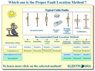
Which one is the Proper Fault Location Method ?. Strongly changing fault resistance. Insulation faults. Flooded cable. Sensitive. Sensitive. Sensitive. Sensitive. Sensitive. Sensitive. Protected. Protected. Protected. Protected. Protected. Protected. Sensitive. Sensitive.

To learn more click on the selected method!
E N D
Presentation Transcript
Which one is the Proper Fault Location Method ? Strongly changing fault resistance Insulation faults Flooded cable Sensitive Sensitive Sensitive Sensitive Sensitive Sensitive Protected Protected Protected Protected Protected Protected Sensitive Sensitive Sensitive Protected Protected Protected ELEKTR NIKA To learn more click onthe selectedmethod!
Disturbers The expected disturbing voltage depends on: A.) The function of neighboring pairs in the cable Intermittent disturbing voltages are expected if the neighboring pairs are used forPOTS DC disturbing voltage is expected ifthe neighboring pairs are used only forISDN No disturbing voltage is expected if the neighboring pairs are used only for data transfer B.) The distance to electrical railway High disturbing AC voltage is expected if the cable is very close to the track Low disturbing AC voltage is expected if the cable is fare enough from the track ELEKTR NIKA
Murray Method in Sensitive mode The Murray method consists of 2 measurements: ■ Measurement of disturbing voltages ■ Bridge measurement with strap on the far end ELQ 30A automatically performs the 2 measurements with the help of the remote controlled switch ELC 30 ELEKTR NIKA
Murray Method in Protected mode The Murray method consists of 2 measurements: ■ Measurement of disturbing voltages ■ Bridge measurement with strap on the far end ELQ 30A automatically performs the 2 measurements with the help of the remote controlled switch ELC 30 ELEKTR NIKA
Küpfmüller Method in Sensitive mode The Küpfmüller method consists of 2 measurements: ■ First measurement with open far end ■ Second measurement with strap on the far end ELQ 30A calculates the Lx/L value from the results of the two measurements The far end can be automatically closed and open with the help of the remote controlled switch ELC 30 ELEKTR NIKA
Küpfmüller Method in Protected mode The Küpfmüller method consists of 2 measurements: ■ First measurement with open far end ■ Second measurement with closed loop ELQ 30A calculates the Lx/L value from the results of the two measurements The far end can be automaticallyclosed and open with the help of the remote controlled switchELC30 ELEKTR NIKA
Repeated Küpfmüller Method in Sensitive mode That method is a sequence of repeated Küpfmüller measurements consisting of 15 part measurements alternating: ■ 8 measurements with open loop (L) ■ 7 measurements with closed loop(K) The far end is automatically closed/open with the help of the remote controlled switch ELC 30 The Lx/L results are displayed in two columns and a histogram When the sequence is completed ELQ 30A selects the acceptable Lx/L results and calculates the average of the accepted results. The unacceptable results are omitted and marked with asterisks. ELEKTR NIKA
Repeated Küpfmüller Method in Protected mode That method is a sequence of repeated Küpfmüller measurements consisting of 15 part measurements alternating: ■ 8 measurements with open loop (L) ■ 7 measurements with closed loop(K) The far end is automatically closed/open with the help of the remote controlled switch ELC 30 The Lx/L results are displayed in two columns and a histogram When the sequence is completed ELQ 30A selects the acceptable Lx/L results and calculates the average of the accepted results. The unacceptable results are omitted and marked with asterisks. ELEKTR NIKA
3-Point (a-b) Method in Sensitive mode Faulty pair FaE Healthy auxiliary wires The 3-Point method consists of 3 measurements: ■ First measurement when the measuring voltage is connected to wire a ■ Second measurement when the measuring voltage is connected to the ground ■ Third measurement when the measuring voltage is connected to wire c ELQ 30Aautomatically performs the 3 measurements with the help of the remote controlled switch ELC 30 ELEKTR NIKA
3-Point (a-b) Method in Protected mode Faulty pair FaE Healthy auxiliary wires The 3-Point method consists of 3 measurements: ■ First measurement when the measuring voltage is connected to wire a ■ Second measurement when the measuring voltage is connected to the ground ■ Third measurement when the measuring voltage is connected to wire c ELQ 30Aautomatically performs the 3 measurements with the help of the remote controlled switch ELC 30 ELEKTR NIKA
3-Point Method in Sensitive mode Faulty wire FaE Healthy auxiliary wires The 3-Point method consists of 3 measurements: ■ First measurement when the measuring voltage is connected to wire a ■ Second measurement when the measuring voltage is connected to the ground ■ Third measurement when the measuring voltage is connected to wire c ELQ 30Aautomatically performs the 3 measurements with the help of the remote controlled switch ELC 30 ELEKTR NIKA
3-Point Method in Protected mode Faulty wire FaE Healthy auxiliary wires The 3-Point method consists of 3 measurements: ■ First measurement when the measuring voltage is connected to wire a ■ Second measurement when the measuring voltage is connected to the ground ■ Third measurement when the measuring voltage is connected to wire c ELQ 30Aautomatically performs the 3 measurements with the help of the remote controlled switch ELC 30 ELEKTR NIKA
ResistanceDifference Measurement in Sensitive mode ELQ 30A automatically performs the measurements with the help of the remote controlled switch ELC 30 ELEKTR NIKA
Resistance Difference Measurement inProtected mode ELQ 30A automatically performs the measurements with the help of the remote controlled switch ELC 30 ELEKTR NIKA
Capacitance Unbalance Measurement in Sensitive mode ELEKTR NIKA
Capacitance Unbalance Measurement in Protected mode ELEKTR NIKA