Download

1 / 47
470 likes | 722 Vues
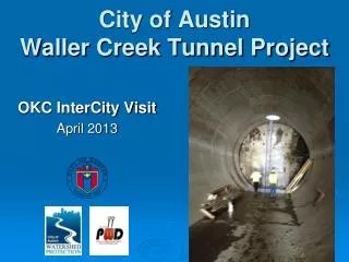
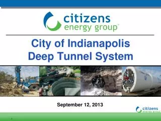
City of Indianapolis Deep Tunnel System. September 12, 2013. Presentation Overview. CSO Deep Tunnel System Efforts to Date Tunnel Project Evaluation Overview Geotechnical Investigations Groundwater Management Plan (GWMP) Schedule and Project Requirements

E N D
City of Indianapolis Deep Tunnel System September 12, 2013 - 1
Presentation Overview • CSO Deep Tunnel System • Efforts to Date • Tunnel Project Evaluation Overview • Geotechnical Investigations • Groundwater Management Plan (GWMP) • Schedule and Project Requirements • DRTC Construction - 2
Indianapolis’ CSO LTCP Overview • Each year, an average of 6 billion gallons of combined sewage overflow into Indianapolis streams • 45-80 times a year, overflows send bacteria, pathogens and untreated waste into: • White River • Fall Creek • Pogues Run • Pleasant Run & Bean Creek • Eagle Creek • Lick Creek & State Ditch - 3
…BUTT, things could be Worse! - 5 Page - 5 01/15/07
Belmont AWTP Indianapolis’ CSO LTCP Overview • City’s CSO Long Term Control Plan is Multi-Faceted and includes: • Using Existing System Capacity • Inflatable Dams and Pinch Valves • Constructing New Storage and Conveyance • Deep Rock Tunnel System • Storage Tanks • Expanding and Upgrading Treatment Facilities • Belmont AWTP • Southport AWTP - 6
Wet Weather Drop Shafts Deep Tunnel System - How it Works Combined Flow to WWTP and Tunnel CSO Outfall Regulators WWTP Consolidation Sewer River To WWTP Combined Sewer SOILS CSO to Tunnel SHALE CSO to Tunnel Working Shaft Storage Tunnel Deep Tunnel Pump Station to WWTP BEDROCK - 7
Deep Tunnel System Details • ~25 miles long • 18-foot finished diameter • Total System Storage of 250 MG min. • 225-275 feet deep in bedrock • 19 drop shafts along FCWRTS • 3 drops shafts DRTC • Flows from Lower Pogues Run and Pleasant Run Tunnels • ~30,000 feet of connection tunnels • 90 MGD deep pump station at Southport AWT - 10
Overview - Geotechnical Investigations • Drilled over 100 Borings Up to 300 Feet Below Ground Surface • Sampling and Testing of Physical Rock and Soil Characteristics • Soil and Groundwater Environmental Screening and Sampling • Hydraulic Packer Testing of Bedrock Permeability Track mounted CME-55 drill rig - 12
Limestone Geologic Contact North Vernon Limestone Jeffersonville Limestone Contact Courtesy of Martin Marietta, Kentucky Avenue Mine. - 16
Solution Features Can Be Risky! Solution (Karstic) Feature Courtesy of Martin Marietta, Kentucky Avenue Mine. - 17
Summary of Geotechnical Findings • Alluvial (Surficial) Soils Ranged from approximately 75 – 100 Feet Thick • Alluvial Soils = Primarily Sand with some Clay and Silt Units • Groundwater Table within 25 feet of Ground Surface • High Hydraulic Conductivities in Surficial Soils based on Pump and Slug Testing • Vertical and Inclined Borings and Rock Cores • Piezometers Set in Vertical Borings • Bi-weekly Monitoring of Groundwater Levels - 18
Summary of Geotechnical Findings • Bedrock Consisted Primarily of Competent Limestone and Dolomite • Shale Underlying the Alluvial Soil on Southern End of Tunnel System (DRTC) • Shale Ranges from 6 – 30+ Feet Thick • Bedrock was Weathered Near Soil/Rock Interface • Bedrock Permeability Fairly Consistent Throughout Deep Bedrock Layers (150+ Feet BGS) • No High Permeability Zones Encountered Below Soil/Rock Interface - 19
Summary of Geotechnical Findings • Rock Quality Designation (RQD) indicates Bedrock is Sound and Relatively Consistent, and Not Heavily Fractured (Phase 1A) • Unconfined Compressive Strength (UCS) averaged 9,000 to 10,000 pounds per square inch (Phase 1A) • In Summary, Rock is Very Favorable for Tunneling - 20
Summary of the Fall Creek/White River Groundwater Management Plan (GWMP) • Overall Goal of the GWMP was to Evaluate Various Scenarios During Tunnel Construction and Future Operation to Determine Any Potential Short-term of Long-term Impacts to Groundwater resources • Regional Cooperation to Evaluate and Monitor Groundwater Levels (Piezometer Readings) • Development and Calibration of an Existing Conditions Groundwater Model • Alternative Scenarios Evaluation • Groundwater Risk Registry - 21
Alternative Scenarios • Primary Considerations • Concerns During Construction (e.g., encountering fractures and potential solution features) • Long Term Operational Impacts of Groundwater • 12 Scenarios Modeled • Scenarios 1-3 – Expected Conditions During Construction • Scenarios 4-6 – High Infiltration During Construction • Scenarios 7-9 – Expected Conditions During Long Term Operation • Scenarios 10-12 – High Infiltration During Long Term Operation - 24
Scenario 1 – White River Tunnel Alignment, Expected Conditions During Construction • Deep Carbonate (Layer 4) - 25
Groundwater Impact Potential (Localized) White River Impact to GW Table Tunnel - 26
Local and Sustainable Project Requirements • Balancing Opportunities and Risk • Not just a Linear Sewer Project - Large Diameter and Complex Tunnel Alternative • Incorporate Sustainable Design Features and Operational Strategies • Green Infrastructure When and Where Appropriate • Begin with the End in Mind (O&M) - 100+ Year System Life Solution • MBE/WBE/Veteran Involvement and Mentoring • Local Execution of Work Preferred • Meet the Revised Consent Decree Schedule - 27
Introducing the Clean Stream Machine! DRTC Project Groundbreaking Event - 28
Deep Rock Tunnel Connector (DRTC) Project • Bid – August 11, 2011 • S-K, JV (J.F. Shea – Kiewit, Joint Venture) • NTP by CEG – December 16, 2011 • Tunnel to be fully lined (full circumference liner) • Participation goals met 15% (M), 8% (W) & 3% (V) • Planned 90 MGD deep rock pump station at launch site • Awarded price - $179,323,115 ( savings of $106,744,660) (8 Miles) • Achievement of Full Operations – December 31, 2017 consent decree schedule - 30
TBM Train - 31
TBM Complexity - 32
Starter Tunnel - 41
Next Steps and Coordination • Project Success • Everybody! • Continuous Coordination • We’re All In this Together • City is Party to the LTCP Consent Decree • Most Near Surface Project are in Street and Parks • Making the Environment Better than when We Started • Improving the City’s Socio-Economic Climate – Value Added • Meaningful and Fair Restoration and Improvements • Other Key Projects Ongoing • FC 01 – Indiana Avenue and 10th Street (April 2013) • WR 06 – Bush Stadium Site (April 2013) - 46
Discussion / Q&A - 47