Network for Earthquake Engineering Simulation (NEES) Design Review
490 likes | 686 Vues
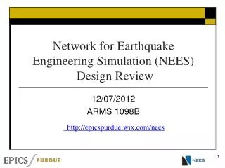
Network for Earthquake Engineering Simulation (NEES) Design Review. 12/07/2012 ARMS 1098B. http://epicspurdue.wix.com/nees. Agenda. Introduction Overview of NEES Clients needs and requirements Project overview Project 1: Shake Table Project 2: Interface Open Discussion.

Network for Earthquake Engineering Simulation (NEES) Design Review
E N D
Presentation Transcript
Network for Earthquake Engineering Simulation (NEES) Design Review 12/07/2012 ARMS 1098B http://epicspurdue.wix.com/nees
Agenda • Introduction • Overview of NEES • Clients needs and requirements • Project overview • Project 1: Shake Table • Project 2: Interface • Open Discussion
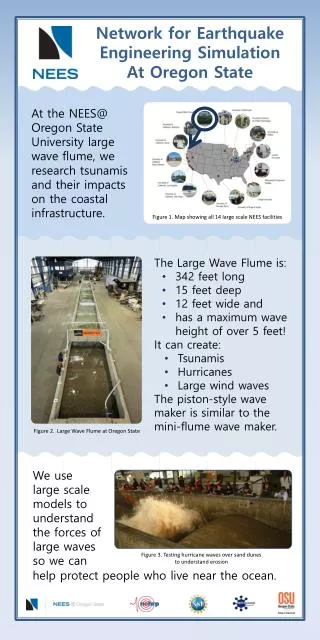
Project Partner NEESNetwork for Earthquake Engineering Simulation 14 Large scale test facilities dedicated to research needed to reduce risks caused by earthquakes and tsunamis
Our clients from NEES Dr. Keith Adams Director of Education Outreach and Training Pamela McClure Education Outreach and Training 207 S. Martin Jischke Dr, Suite 301 West Lafayette, In 47907
NEES EOT – Client Goals • Increase public awareness of NEES, its research and its mission • Bring science and engineering to classrooms • Raise student’s interest in earthquake engineering and science 5
Popular NEES Outreach ActivityMake Your Own Earthquake System PC Display PC Platform w/ accelerometer Developed at UC Santa Barbara by Dr. Sandra Seale
Existing Commercial Shake Table • Current use of MTS shake Table • Demonstrate dynamic motion • Be used with design competitions • Constraints • expensive, immobile
General Goals • Develop a low cost, controlled motion table (shake table) • Supports three modes • Harmonic motion with variable frequency and amplitude • Make your own earthquake input to control motion • Replicate prior earthquake motion
Customer’s Goal • Forced motion system Physical Models Interface Visual display and controller Shake table Table Jump Platform Sensor Power 10
Shaketable Team • Project Leader • Bryan Routt- Freshman, Engineering • Project Members • Sarah Hacker- Freshman, Engineering • Sami Labban- Freshman, Engineering (Partner Liason) • Harsh Limbasia- Freshman, Engineering • Karan Talathi- Freshman, Engineering • Kenneth Holmes- Freshman, Engineering • Alexander Newman- Freshman, Engineering
Target performance • Demonstrate side by side performance of two 5 story KNEX models equipped with • Tune mass damper • Cross bracing support
Shaketable Structure • 80/20 Aluminum Frame • Inexpensive • Easy to assemble • Very sturdy
Shaketable Structure • Suction Cup Feet • Simple way to mount the whole structure to a surface. • Very cheap and easy to use.
Shaketable Structure • Rails • Repurposed original rail mounts • Added small ¼ inch square to bolt on to 80/20 frame. EPICS
Shaketable Structure • Aluminum Back Plate • Sturdy mount for MDF wall and motor • Clean look for the outside of the structure.
Shaketable Structure • Motor Mount • Motor sits in ¼ deep hole • Screws run all the way through from the outside aluminum plate into the back of the motor.
Shaketable Structure • Rack and Pinion • Rack epoxied to plate on bottom of slider • Allows for slider to be reused in future designs.
Mounting Platform • Original peg board from MTS powered table • Works well with K’nex system • Board screws into shaketable platform so it can be removed and exchanged for another part • Relatively easy to make and durable
Component Mounting • Components to be Mounted • Arduino board • Motor driver • Motor • Components mounted to maximize space between components. • Isolate electronic components from Board • Rubber Spacers • Screws into MDF backplane
EPICS NEES Interface Design Jingye Liu(Project leader) Dongyang Fu Zachary Golden Andrew Grosinger NikhilgandhiManojkumar
Introduction • Overview • Microcontroller • Driver Circuit • Circuit Shield • User Interface
Overview Laptop Visual Feeback Input requests (microC power) Mount/ Housing Mounting microC High current Accelerometer Sensor Signal and Power Low current signal Motor driver Motor Power
Enhancement for the MYOE Physical Models Visual Display Mounting Mechanism User Interface Controller Interface Shaking Platform Jumping Platform Sensor Input QNC? Motion Mechanism
Accelerometer • ADXL 335 • Measure acceleration from jump platform • Send signal to micro controller
Microcontroller and Code • Receive Frequency from Accelerometer/Manual User Input • Convert Frequency • Send Command to Driver Circuit • Control Direction of the Motor • Code in “Sketch”
Micro Controller Logic Harmonic Mode No Yes Compute steps Move Motor Check inputs Update Display Stop ? Start And Wait for Input Yes Read Sensor Data Compute Steps and Move Motor Accordingly Check inputs Update Display Stop ? MYOE Mode No
Driver Circuit • Two Options for Motor Driver • Stepper Motor Current ROB-10267
Wiring Interface ACC 2 Motor Driver ACC 1 Shield Mounted G 5v X1 Y1 Z1 X2 Y2 Z2 Arduino 8 9
Graphic Interface Computer C#
Value Added Project • Team investigated to extension to the project • Alternative low cost, controlled motion control table • Accelerometer Mounting on K’nex structures
Premise • Could the existing low cost version be interfaced with the controlled motion system? • Issues • Need to increase durability • Potential to improve portability
Make Up • PVC Base • Modified aluminum drawer slides • Plywood on drawer slides • Bungees on underside to counter input force and center table. • Motion control • Hand operated • DC motor and off-center CAM – controlled by Arduino system designed by interface team.
Parts • PVC pipes (1.5’ x 1.5’ x 1.5’’) and 90ᵒ Elbows • PVC cement • Ply Wood (1.5’ x 1.5’) • Bungees • Screws • Bolts • Drawer Slides (1.5’ long) • Aluminum Straps • Aluminum Strips (May not need) • Suction Cups • Total Cost: $56
Convenience for Teachers • Drawer slides stop so the board does not slide too far when carrying it • Easily Assembled with easy parts to work with (PVC and Wood) • Able to shake with hand and with motor if available • Easy to use • Safe (Plus more safety tips in manual)
Three Part Manual • How To Build It • Notes On Alternate Parts • How It Works • Notes On Convenience • Safety • Notes On Having It Around Children
Goal • Leverage the input capabilities of the microcontroller to increase potential to gather more data about an experiments • Target multiple accelerometer inputs • Base platform • Structure
Mounting Positions Position 3 Position 1 Position 2
Final Conclusions • Short term: Stick pads and shrink wrap • Long term: Pocket-hook holder • Best mounting position – Position number 3