Download
1 / 34
340 likes | 463 Vues
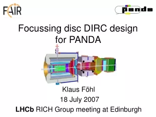
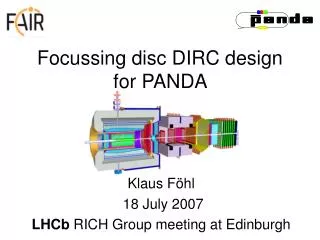
Focussing disc DIRC design for PANDA. Klaus F öhl 18 July 2007 LHCb RICH Group meeting at Edinburgh. HESR. Rare-Isotope Beams N-N Collisions at High Energy Ion Beam Induced Plasmas Antiprotons. Nuclei Far From Stability Compressed Nuclear Matter High Energy Density in Bulk

E N D
Focussing disc DIRC design for PANDA Klaus Föhl 18 July 2007 LHCb RICH Group meeting at Edinburgh
HESR Rare-Isotope Beams N-N Collisions at High Energy Ion Beam Induced Plasmas Antiprotons Nuclei Far From Stability Compressed Nuclear Matter High Energy Density in Bulk Hadron Spectroscopy
Core programme of PANDA (1) • Hadron spectroscopy • Charmonium spectroscopy • Gluonic excitations (hybrids, glueballs) • Charmed hadrons in nuclear matter • Double -Hypernuclei
PANDA Side View • High Rates • 107 interaction/s • Vertexing • KS0, Y, D, … • Charged particle ID • e±, μ±, π±, K, p,… • Magnetic tracking • EM. Calorimetry • γ,π0,η • Forward capabilities • leading particles • Sophisticated Trigger(s) Pbar ANDA AntiProton ANihilations at DArmstadt
PANDA Detector Top View beam
PANDA Detector Top View Barrel-DIRC RICH beam Endcap Disc DIRC
fused silica radiator Cherenkov Detectors in PANDA • HERMES-style RICH • BaBar-style DIRC • Disc DIRC 2-dimensional imaging type * measurement 4 instead of 2 mirrors * measurement * one-dimensional imaging DIRC type * * side view front view
Focussing & Chromatic Correction focussing element
Focussing & Chromatic Correction higher dispersion glass SiO2 amorphous fused silica
Focussing & Chromatic Correction higher dispersion glass different curvatures required internal reflection angle independent of curvature is compromise two boundary surfaces to turn correction mostly angle-independent light never leaves dense optical medium good for phase space
Focussing disc DIRC focal plane of focussing lightguide with rectangular photon detector pixels SiO2 LiF lightguide “200mm” focal plane coord. [mm] SiO2 lightguide number
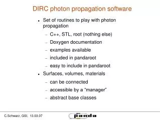
Light Generation • radiator thickness • number of photons • transparency • wide wavelength range (eV) – high statistics • material dispersion • either narrow w. band • or correction required
( ) ( ) ( ) x x x x x Particle Path Straggling 2 sigma envelopes standard deviation of K fused silica, thickness?? Cherenkov ring angle information of upstream tracking is 0.57 off Cherenkov ring image is blurred by 0.38 reduce radiator thickness, reduce X0
10 mrad about 50-100 reflections individual angle variations: = Pixel /sqrt(N) d Fresnel Zone Light Propagation 1 mrad length 400mm, =400nm d=1mm (approximately) rough surface causing path length differences and phase shifts
Expansion Volume advantageous peripheral tracks create local high photon density outer limit of acceptance coverage increasing particle angle rim proximity the further outward, the more radial the light paths performance does drop towards disc perimeter
focal plane 100mm pixel width 2-3mm benign optics thicker plate ok Focussing Lightguides • short focal plane 50mm • ~1mm pixels needed • optical errors exist • thicker plate a problem
detector geometry magnetic field (~1T) photon rate (MHz/pixel) light cumulative dose radiation dose Light Detection photon detection is a problem still to be solved
Focussing disc DIRC rectangular pixel shape focussing is better than 1mm over the entire line chosen as focal plane SiO2 LiF for dispersion correction has smaller |dn/d| than SiO2 LiF lightguide “200mm” light stays completely within medium all total reflection compact design all solid material flat focal plane focal plane coord. [mm] radiation-hard “glass” RMS surface roughness at most several Ångström lightguide number
Momentum Thresholds p n=1.47 K p K aerogel n=1.05 p K total internal reflection limit fused silica n=1.47
Detector Performance simulation example with 2 fit analysis short lightguide 125mm, focal plane 48mm p2-p1= 4x(1/2 + 2/2) n_lightguides= 192 lightguidewidth= 25 lightguidelength= 65 (from apex) lightguide focal plane = [32,80] lightguide pixel size= 1 z_from_target[mm]= 2000 disc_radius[mm]= 1100 disc_thickness[mm]= 10 nzero[1/mm]= 14 (0.4eV) LiF corrector plate radiation_length[mm]= 126 B [Tesla] = 2 momentum[GeV/c]= 5 beta= 0.98
In brief • fused silica radiator disc, around the rim: • LiF plates for dispersion correction • internally reflecting focussing lightguides • one-dimensional imaging DIRC • radiator with very good RMS roughness required • perfect edges (as in the BaBar DIRC) not needed • number-of-pixels ~ p4 • stringent requirements for photon detectors • two alternative designs, one DIRC, one RICH • two examples of material tests working on Cerenkov detectors for PANDA: Edinburgh, GSI, Erlangen, Gießen, Dubna, Jülich, Vienna, Cracow, Glasgow
Time-of-Propagation design M. Düren, M. Ehrenfried, S. Lu, R. Schmidt, P. Schönmeier single photon resolution ~30-50ps needed relevant for ToP • idea: • reflect some • photons • several path lengths mirrors t [ps] reflective hole [deg]
Proximity Focussing design suggestion Lars Schmitt: combine tracking and PID design variation with mirror and the expansion volume upstream radiator placed closer to EMC C6F14 CsI + GEM
Material Test (1) Testing transmission and total internal reflection of a fused silica sample (G. Schepers and C. Schwarz, GSI)
Material Test (2) Irradiation test at KVI Schott LLF1 HT glass sample (B. Seitz, M. Hoek, Glasgow)
Particle ID & Kinematics - + + K K K K even or K - + + - pp KK T=5,10,15 GeV/c pp DD D Kpp T=6.6 GeV/c + + - + + - - + + + pp i.e. charmonium production + D distinguish and K (K and p) ... if mass known, particle identified need to measure two quantities: dE/dx energy momentum velocity momentum (tracking in magnetic field) velocity (Cherenkov Radiation) momentum (tracking in magnetic field) velocity (Cherenkov Radiation)
Focussing Lightguides no LiF plate
Time-of-Propagation TOP =30ps N0=344 n0=7.64/mm
Time-of-Propagation comparison: hexagon 960mm width or round disc 1100mm radius TOP =70ps N0=344 n0=17.19/mm [ref: Markus Ehrenfried, Saclay talk] t=30ps hexagon with rectangular hole hexagon mirror rectangle circle mirror rectangle hexagon black rectangle circle black rectangle circular with rectangular hole
Time-of-Propagation these calculations: =400nm-800nm Quantum Efficiency 30% n0=17.19/mm per band: n(group)=0.0213 (inspired by [480nm-600nm] n=0.00615 • single photo timing crucial • performance increase comes with more tracks in the time-angle-plane reflective hole absorbing hole 16 deg
Proximity Focussing radiator 15mm expansion 135mm [no] mirror C6F14+ CsI+GEM beware: no reality factors included yet