3D Vision
3D Vision. CSC I6716 Spring 2004. Topic 7 of Part 2 Stereo Vision (I). Zhigang Zhu, NAC 8/203A http://www-cs.engr.ccny.cuny.edu/~zhu/VisionCourse-2004.html. Stereo Vision. Problem Infer 3D structure of a scene from two or more images taken from different viewpoints


3D Vision
E N D
Presentation Transcript
3D Vision CSC I6716 Spring 2004 Topic 7 of Part 2 Stereo Vision (I) Zhigang Zhu, NAC 8/203A http://www-cs.engr.ccny.cuny.edu/~zhu/VisionCourse-2004.html
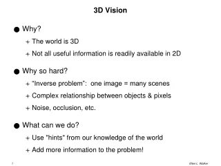
Stereo Vision • Problem • Infer 3D structure of a scene from two or more images taken from different viewpoints • Two primary Sub-problems • Correspondence problem (stereo match) -> disparity map • Similarity instead of identity • Occlusion problem: some parts of the scene are visible only in one eye • Reconstruction problem -> 3D • What we need to know about the cameras’ parameters • Often a stereo calibration problem • Lectures on Stereo Vision • Stereo Geometry – Epipolar Geometry (*) • Correspondence Problem (*) – Two classes of approaches • 3D Reconstruction Problems – Three approaches
A Stereo Pair • Problems • Correspondence problem (stereo match) -> disparity map • Reconstruction problem -> 3D 3D? ? CMU CIL Stereo Dataset : Castle sequence http://www-2.cs.cmu.edu/afs/cs/project/cil/ftp/html/cil-ster.html
More Images… • Problems • Correspondence problem (stereo match) -> disparity map • Reconstruction problem -> 3D
More Images… • Problems • Correspondence problem (stereo match) -> disparity map • Reconstruction problem -> 3D
More Images… • Problems • Correspondence problem (stereo match) -> disparity map • Reconstruction problem -> 3D
More Images… • Problems • Correspondence problem (stereo match) -> disparity map • Reconstruction problem -> 3D
More Images… • Problems • Correspondence problem (stereo match) -> disparity map • Reconstruction problem -> 3D
Lecture Outline • A Simple Stereo Vision System • Disparity Equation • Depth Resolution • Fixated Stereo System • Zero-disparity Horopter • Epipolar Geometry • Epipolar lines – Where to search correspondences • Epipolar Plane, Epipolar Lines and Epipoles • http://www.ai.sri.com/~luong/research/Meta3DViewer/EpipolarGeo.html • Essential Matrix and Fundamental Matrix • Computing E & F by the Eight-Point Algorithm • Computing the Epipoles • Stereo Rectification
P(X,Y,Z) Stereo Geometry • Converging Axes – Usual setup of human eyes • Depth obtained by triangulation • Correspondence problem: pl and pr correspond to the left and right projections of P, respectively.
disparity Depth Z Elevation Zw A Simple Stereo System LEFT CAMERA RIGHT CAMERA baseline Right image: target Left image: reference Zw=0
Image plane Image plane pl(xl,yl) pr(xr,yr) f = focal length f = focal length Optical Center Ol Optical Center Or LEFT CAMERA RIGHT CAMERA Disparity Equation P(X,Y,Z) Stereo system with parallel optical axes Depth Disparity: dx = xr - xl B = Baseline
Image plane pr(xr,yr) Image plane f = focal length pl(xl,yl) f = focal length Optical Center Or Optical Center Ol LEFT CAMERA RIGHT CAMERA Disparity vs. Baseline P(X,Y,Z) Stereo system with parallel optical axes Depth Disparity dx = xr - xl B = Baseline
Two viewpoints Ol Or Z1 Z2 Z1 Z2>Z1 Depth Accuracy • Given the same image localization error • Angle of cones in the figure • Depth Accuracy (Depth Resolution) vs. Baseline • Depth Error 1/B (Baseline length) • PROS of Longer baseline, • better depth estimation • CONS • smaller common FOV • Correspondence harder due to occlusion • Depth Accuracy (Depth Resolution) vs. Depth • Disparity (>0) 1/ Depth • Depth Error Depth2 • Nearer the point, better the depth estimation • An Example • f = 16 x 512/8 pixels, B = 0.5 m • Depth error vs. depth Absolute error Relative error
Stereo with Converging Cameras • Stereo with Parallel Axes • Short baseline • large common FOV • large depth error • Long baseline • small depth error • small common FOV • More occlusion problems • Two optical axes intersect at the Fixation Point • converging angle q • The common FOV Increases FOV Left right
FOV Left right Stereo with Converging Cameras • Stereo with Parallel Axes • Short baseline • large common FOV • large depth error • Long baseline • small depth error • small common FOV • More occlusion problems • Two optical axes intersect at the Fixation Point • converging angle q • The common FOV Increases
Stereo with Converging Cameras Fixation point • Two optical axes intersect at the Fixation Point • converging angle q • The common FOV Increases • Disparity properties • Disparity uses angle instead of distance • Zero disparity at fixation point • and the Zero-disparity horopter • Disparity increases with the distance of objects from the fixation points • >0 : outside of the horopter • <0 : inside the horopter • Depth Accuracy vs. Depth • Depth Error Depth2 • Nearer the point, better the depth estimation FOV q Left right
Stereo with Converging Cameras Fixation point • Two optical axes intersect at the Fixation Point • converging angle q • The common FOV Increases • Disparity properties • Disparity uses angle instead of distance • Zero disparity at fixation point • and the Zero-disparity horopter • Disparity increases with the distance of objects from the fixation points • >0 : outside of the horopter • <0 : inside the horopter • Depth Accuracy vs. Depth • Depth Error Depth2 • Nearer the point, better the depth estimation Horopter q al ar ar = al da = 0 Left right
Stereo with Converging Cameras Fixation point • Two optical axes intersect at the Fixation Point • converging angle q • The common FOV Increases • Disparity properties • Disparity uses angle instead of distance • Zero disparity at fixation point • and the Zero-disparity horopter • Disparity increases with the distance of objects from the fixation points • >0 : outside of the horopter • <0 : inside the horopter • Depth Accuracy vs. Depth • Depth Error Depth2 • Nearer the point, better the depth estimation Horopter q al ar ar > al da > 0 Left right
Stereo with Converging Cameras Fixation point • Two optical axes intersect at the Fixation Point • converging angle q • The common FOV Increases • Disparity properties • Disparity uses angle instead of distance • Zero disparity at fixation point • and the Zero-disparity horopter • Disparity increases with the distance of objects from the fixation points • >0 : outside of the horopter • <0 : inside the horopter • Depth Accuracy vs. Depth • Depth Error Depth2 • Nearer the point, better the depth estimation Horopter ar aL ar < al da < 0 Left right
Stereo with Converging Cameras Fixation point • Two optical axes intersect at the Fixation Point • converging angle q • The common FOV Increases • Disparity properties • Disparity uses angle instead of distance • Zero disparity at fixation point • and the Zero-disparity horopter • Disparity increases with the distance of objects from the fixation points • >0 : outside of the horopter • <0 : inside the horopter • Depth Accuracy vs. Depth • Depth Error Depth2 • Nearer the point, better the depth estimation Horopter al ar D(da) ? Left right
P Pl Pr Yr p p r l Yl Xl Zl Zr fl fr Ol Or R, T Xr Parameters of a Stereo System • Intrinsic Parameters • Characterize the transformation from camera to pixel coordinate systems of each camera • Focal length, image center, aspect ratio • Extrinsic parameters • Describe the relative position and orientation of the two cameras • Rotation matrix R and translation vector T
P Pl Pr Yr p p r l Yl Zl Zr Xl fl fr Ol Or R, T Xr Epipolar Geometry • Notations • Pl =(Xl, Yl, Zl), Pr =(Xr, Yr, Zr) • Vectors of the same 3-D point P, in the left and right camera coordinate systems respectively • Extrinsic Parameters • Translation Vector T = (Or-Ol) • Rotation Matrix R • pl =(xl, yl, zl), pr =(xr, yr, zr) • Projections of P on the left and right image plane respectively • For all image points, we have zl=fl, zr=fr
P Pl Pr Epipolar Plane Epipolar Lines p p r l Ol el er Or Epipoles Epipolar Geometry • Motivation: where to search correspondences? • Epipolar Plane • A plane going through point P and the centers of projection (COPs) of the two cameras • Conjugated Epipolar Lines • Lines where epipolar plane intersects the image planes • Epipoles • The image in one camera of the COP of the other • Epipolar Constraint • Corresponding points must lie on conjugated epipolar lines
Essential Matrix • Equation of the epipolar plane • Co-planarity condition of vectors Pl, T and Pl-T • Essential Matrix E = RS • 3x3 matrix constructed from R and T (extrinsic only) • Rank (E) = 2, two equal nonzero singular values Rank (S) =2 Rank (R) =3
Essential Matrix • Essential Matrix E = RS • A natural link between the stereo point pair and the extrinsic parameters of the stereo system • One correspondence -> a linear equation of 9 entries • Given 8 pairs of (pl, pr) -> E • Mapping between points and epipolar lines we are looking for • Given pl, E -> pr on the projective line in the right plane • Equation represents the epipolar line of either pr (or pl) in the right (or left) image • Note: • pl, pr are in the camera coordinate system, not pixel coordinates that we can measure
Fundamental Matrix • Mapping between points and epipolar lines in the pixel coordinate systems • With no prior knowledge on the stereo system • From Camera to Pixels: Matrices of intrinsic parameters • Questions: • What are fx, fy, ox, oy ? • How to measure pl in images? Rank (Mint) =3
Fundamental Matrix • Fundamental Matrix • Rank (F) = 2 • Encodes info on both intrinsic and extrinsic parameters • Enables full reconstruction of the epipolar geometry • In pixel coordinate systems without any knowledge of the intrinsic and extrinsic parameters • Linear equation of the 9 entries of F
Computing F: The Eight-point Algorithm • Input: n point correspondences ( n >= 8) • Construct homogeneous system Ax= 0 from • x = (f11,f12, ,f13, f21,f22,f23 f31,f32, f33) : entries in F • Each correspondence give one equation • A is a nx9 matrix • Obtain estimate F^ by SVD of A • x (up to a scale) is column of V corresponding to the least singular value • Enforce singularity constraint: since Rank (F) = 2 • Compute SVD of F^ • Set the smallest singular value to 0: D -> D’ • Correct estimate of F : • Output: the estimate of the fundamental matrix, F’ • Similarly we can compute E given intrinsic parameters
el lies on all the epipolar lines of the left image P Pl Pr For every pr Epipolar Plane F is not identically zero Epipolar Lines p p r l Ol el er Or Epipoles Locating the Epipoles from F • Input: Fundamental Matrix F • Find the SVD of F • The epipole el is the column of V corresponding to the null singular value (as shown above) • The epipole er is the column of U corresponding to the null singular value • Output: Epipole el and er
P Pl Pr p’ r p’ l Y’l Y’r Z’r Z’l X’l T X’r Ol Or Stereo Rectification • Stereo System with Parallel Optical Axes • Epipoles are at infinity • Horizontal epipolar lines • Rectification • Given a stereo pair, the intrinsic and extrinsic parameters, find the image transformation to achieve a stereo system of horizontal epipolar lines • A simple algorithm: Assuming calibrated stereo cameras
P Pl Pr Yr p p r l Yl Xl Zl Zr X’l T Ol Or R, T Xr Xl’ = T, Yl’ = Xl’xZl, Z’l = Xl’xYl’ Stereo Rectification • Algorithm • Rotate both left and right camera so that they share the same X axis : Or-Ol = T • Define a rotation matrix Rrect for the left camera • Rotation Matrix for the right camera is RrectRT • Rotation can be implemented by image transformation
P Pl Pr Yr p p r l Yl Xl Zl Zr X’l T Ol Or R, T Xr Xl’ = T, Yl’ = Xl’xZl, Z’l = Xl’xYl’ Stereo Rectification • Algorithm • Rotate both left and right camera so that they share the same X axis : Or-Ol = T • Define a rotation matrix Rrect for the left camera • Rotation Matrix for the right camera is RrectRT • Rotation can be implemented by image transformation
P Pl Pr p’ r p’ l Y’l Y’r Zr Z’l X’l T X’r Ol Or R, T T’ = (B, 0, 0), P’r = P’l – T’ Stereo Rectification • Algorithm • Rotate both left and right camera so that they share the same X axis : Or-Ol = T • Define a rotation matrix Rrect for the left camera • Rotation Matrix for the right camera is RrectRT • Rotation can be implemented by image transformation
Next • Two Primary Sub-problems in Stereo Vision • Correspondence problem • 3D reconstruction from stereo Stereo Vision (II) • Homework #3 online, Due April 13 before midnight