Download
1 / 27
270 likes | 506 Vues
Plant Wide Controller (PWC) Overview. Preferred Instruments a division of Preferred Utilities Mfg. Corp. Plant Wide Controller.

E N D
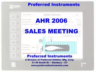
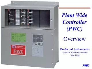
Plant Wide Controller (PWC) Overview Preferred Instruments a division of Preferred Utilities Mfg. Corp.
Plant Wide Controller The Plant Wide ControllerTM (PWC) is a state-of-the-art boiler sequencing, control and monitoring system. The PWC combines innovative ease of operation, communication and expansion capabilities with boiler application expertise. Off-the-shelf, standard modulating Lead-Lag applications can be expanded to control circulating water variable speed pumps and isolation valves while monitoring the flame safeguard and boiler control systems.
Easy to Operate Key lockable Door Security
Hardwired Control Switches & Indications: Easy to Operate Firing Rate Control Dial Firing Rate Auto / Man 0 - 100 % Bargraph Boiler On-Off-Auto Status Indications
Easy to use displays for: Boiler Plant Control & Monitoring Historical Trending Alarm & Event Handling Boiler Plant Setup Easy to Operate LCD Graphic Display and Keypad
Home Page - Boiler Overview Display Arrow Keys - Move Cursor Menu, Page Up, Down - Display Selection Alarm List - Alarm, Event Display Alarm Silence PB Easy to Operate Display Keys
Lead / Lag Control Start Qty Control Sequence Control Custom Lead Rotate Alarm Status Time / Date Stamped Header Status Pressure / Temperature Setpoint Outside Temperature Home Page • Status • Started Boilers • Warming Boilers • Modulating Boilers • Tripped Boilers
Up to 200 Alarms & Events First in - First out Operator Actions Events Alarms Time & Date Stamped Alarm & Event Summary
An Essential Monitoring Tool Multiple(4) Pen “Charts” 8 min, 40 min., and 2, 8, & 24 hour charts Historical Trending • 8 channel, 2 Hr Historical Memory - Standard • 32 Mb Historical Memory - Optional • 32 ch AI + 32 ch DI every 15 seconds for 30 days • 90 or more days for less channels with low activity (depends on data compression efficiency)
Fill In The Blanks Boiler Sequence PID Tuning Outdoor Reset Setup Day / Night Setback Day / Week Setback Week / Year Setback Easy Setup
Easily Configured: Normal Setpoints Setback Setpoints High & Low Limits Outdoor Cutoff Automatic Graphical Representation Outdoor Reset / Setback Temp.
PWC Front Door Open (2 to 5 boiler lead / lag configuration shown with three spare slots) EXPANDABLE
CPU Board • (2) Analog Inputs (4-20 mAdc /Thermistor) • (1) Relay Output (SPDT, 8A) • (1) RS232 programming Port • (1) Isolated RS485 Port • (Modbus or Bacnet Option) • (1) Telephone Modem Option Card • Dial in or dial out, 33.6 kb, RJ-11 jack, Data and Pagers • (1) Printer Port (Alarms / Logs)
Discrete Input • (15) Inputs, 120 Vac, optically isolated • (5) groups of isolated neutrals • (15) LED status indications • (2) 2A / 120 Vac Fuses
Hand-Off-Auto Relay Output • (5) Relay Outputs • (8A inductive, 1/2 Hp, 120 Vac) • (5) Hand-Off-Auto Toggle Switches • Toggle Switch is directly wired into output circuit. • (5) LED's for Output ON / OFF • (5) LED's for ”Call for Operation” • (2) 2A / 120 Vac Fuses
Auto/Manual Analog Output • (5) Modulating Analog Outputs • (5) Auto-Manual Toggle Switches • "Manual" hardware overrides CPU • Bumpless Manual to Auto Transfer • (5) 0-100% Output Control Knobs • (5) 0-100% Output Bargraphs • Requires (1) Output Card per active channel, Any combination of 4-20 mA and 135 ohm cards
Analog Input • (8) UNIVERSAL Inputs • Switch Selectable as: • 2 wire 4-20 mA, with internal 24 Vdc • Thermistor, -60F - 300 F • Thermocouple, Type J, 0 - 1200 F, • 0-5 Vdc, potentiometers and other signals • Pulse, 0.6 ppm - 4000 Hz, 0-15 Vdc pulsers for Oil, Gas, Water, & kWh meters • Enables Fuel Budget Fuel Consumption Tracking • (8) LED status indications • Power Ouputs and Signal Inputs are short circuit protected
Relay Output • (8) Isolated Relay Outputs • ( 8A inductive, ½ Hp, 120 Vac) • (2) SPDT, (6) NO-SPST • (8) LED status indications • (2) 2A / 120 Vac Fuses
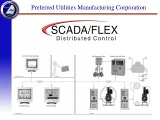
To Customer’s Building Automation Systems (Modbus / Bacnet) Communications Pagers (Modbus / Bacnet) Diesels Chillers etc. Boilers
Advanced Communication Capability • Communications • Modbus communication to BAS or SCADA • Dial In From PC • Dial Out to Alpha Numeric Pager
Availability • Hard Service Manual • Every Boiler Start / Stop Command & Firing Rate can be set manually in the unlikely event of a CPU hardware failure or software corruption • A CPU failure will not prevent central manual control of the boiler plant • This is a UNIQUE FEATURE! • Fault Monitoring • Analog Inputs (thermisters, 4-20mA signals) are monitored & LED used to show fault status
Installation Spare Terminals (typical) Physical Separation Between Operation and Wiring Screwed fast Cable Tie Downs 3/4” conduit connections Power Fuses
Preferred Instruments Preferred Instruments 31-35 South Street • Danbury • CT T: (203) 743-6741 • F: (203) 798-7313 www.preferred-mfg.com