Preferred Utilities Manufacturing Corp
730 likes | 908 Vues
Preferred Utilities Manufacturing Corp. Combustion Theory Boiler Efficiency And Control. Preferred Utilities Manufacturing Corporation 31-35 South St. • Danbury • CT T: (203) 743-6741 F: (203) 798-7313 www.preferred-mfg.com. Overview. Introduction Combustion Basics

Preferred Utilities Manufacturing Corp
E N D
Presentation Transcript
Preferred Utilities Manufacturing Corp Combustion Theory Boiler Efficiency And Control Preferred Utilities Manufacturing Corporation 31-35 South St. • Danbury • CT T: (203) 743-6741 F: (203) 798-7313 www.preferred-mfg.com
Overview • Introduction • Combustion Basics • Efficiency Calculations • Control Strategy Advantages and Disadvantages • Summary
Preferred Utilities Manufacturing Corp. • Over 80 Years of Combustion Experience • Custom Engineered Combustion Solutions • Package Burners for Residual Oil, Distillate Oil and Natural Gas • Fuel Handling Systems for Residual Oil Burners • Fuel Handling Systems for Distillate Oil Burners • Diesel Engine Fuel Management Systems • Combustion Control Systems • Burner Management Systems • Data Acquisition Systems
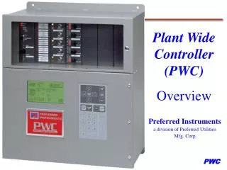
Instrumentation & Control Products DCS-III Programmable Controller Plant Wide Controller PCC-III Multiple Loop Controller Draft Control
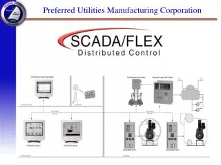
Operator Interface JC-10D Process Bargraph Display PCC-III Faceplate Display SCADA/Flex Distributed Control Station LCD Message Display OIT10 Operator Interface Terminal
Sensors HD-A1 Tank Gauge Leak Detector Pressure Sensor Outdoor Air Temperature Sensor Tank Gauge Level Sensor ZP Oxygen Probe PCC-300 EPA Opacity Monitor JC-30D Opacity Monitor
PCC-III Combustion Experience Boiler Specific... • Operator Friendly • F(x) Characterizers with “Learn” Mode • Built In Boiler Efficiency • Constructed For Boiler Front Mounting • 120 Vac Inputs for Direct BMS Interface • Triac Outputs to Drive Electric Actuators • Free Standard Combustion Blockware • There are many digital controller manufacturers, but NONE have Preferred’s in-depth and ongoing combustion control experience.
UtilitySaverTM Burner Control • The UtilitySaver includes firing rate control with both oxygen trim and variable speed fan combustion air flow control. • UtilitySaverfuel and electrical savings can pay for the installed system in two years or less. Fuel and Electrical Savings…
BurnerMate Touch Screen Fully Integrated Touch Screen…
BurnerMate Touch Screen DCS-III Controller…
BurnerMate TS Advanced Communication…
BurnerMate Touch Screen Easy Operation…
BurnerMate Touch Screen Easy Setup…
Combustion Basics • What is fuel made of? • What is air made of? • What happens when fuel is burned? • Where does the energy go? • What comes out the smoke stack?
Most Fuels are Hydrocarbons • Common fuels have “typical” analysis • can be used for most combustion calculations • especially for natural gas • also number 2 fuel oil • Residual oil can be approximated with a typical fuel oil analysis • Wood, coal, waste require a case by case chemical analysis for combustion calculations
Common Fuels Analysis Typical Ultimate Analysis of Common Fuels Percent by Weight
Composition of (Dry) Air • By Volume • 20.95% Oxygen, O2 • 79.05% Nitrogen, N2 • By Weight • 23.14% Oxygen • 76.86% Nitrogen • Can be up to 9% H2O by volume in Summer • Traces of Argon and CO2
Common Combustion Reactions • Neglecting H2O in Air • Neglecting NOx, Other minor reactions • Simplifying percentages: 4N2 + O2 + 2H2Þ 2H2O + 4N2 + Heat 4N2 + O2 + C Þ CO2 + 4N2 + Heat 4N2 + O2 + S Þ SO2 + 4N2 + Heat
Common Combustion Reactions • For Methane CH4 + 2O2Þ CO2 + 2H2O + Heat 16 + 64 Þ 44 + 36 Therefore: #O2 Required = 64 # Fuel = 16 Therefore #O2/#Fuel =4/1 or 4
Boiler Efficiency and Control • Boiler efficiency is computed “by losses” • Understanding of efficiency calculations helps in choosing the proper control strategy • Energy “traps” such as economizers can provide a payback • Preferred Instruments has over 75 years of combustion experience to help optimize boiler efficiency
Boiler Efficiency “by Losses” • Conservation of Energy • Fuel energy in equals heat energy out • Energy leaves in steam or in losses • Efficiency = 100% minus all losses • Typical boiler efficiency is 80% to 85% • The remaining 15% to 20% is lost • Largest loss is a typical 15% “stack loss” • Radiation loss may be 3% at full input • Miscellaneous losses might be 1 to 2%
Stack Losses • Latent heat of water vapor in stack • Fixed amount depending on hydrogen in fuel • About 5% of fuel input for fuel oil • About 9% of fuel input for natural gas • Assumes a non-condensing boiler (typical) • Sensible heat of stack gasses • Typically around 10% of fuel input • Increased mass flow and stack temperature increase the loss
Radiation Loss • Generally a fixed BTU / hour heat loss • As a percentage, is greater at low fire • Depends on the boiler construction • Is generally about a 3% loss at high fire • Would be 12% loss at 25% of fuel input
Miscellaneous Losses • Consist of: • blow down losses • unburned fuel losses (carbon in ash or CO) • Generally on the order of one percent
Effects of Stack Temperature • Generally, stack temperature is: • Steam temperature plus 100 to 200 degrees F • Rule of thumb – watertube-150, firetube-100F • Higher for dirty boilers, higher loads and increased excess air levels • A 100 degree increase in stack temperature • Costs about 2.5% in energy losses • May mean the boiler needs serious maintenance • Economizers are useful on medium and high pressure boilers as an energy “trap”
Oxygen and Air Required for Gas • To release 1 million BTU with gas • 42 lbs. of gas are burned • 168 lbs. of oxygen are required no excess air • 725 lbs. of combustion air • 767 lbs. of stack gasses are produced • 5% to 20% excess air is required by burner • Each additional 10% increase in excess air: • Adds 73 lbs. of stack gasses • Reduces efficiency by 1% to 1.5%
Cost of Inefficiency • The combined effects of extra excess air and the resulting increase in stack temperature: • Could mean a 2% to 10% efficiency drop • Reducing this “extra” excess air saves fuel • Savings = (Fuel Cost)*[(1/old eff)-(1/new eff)] • For a facility with a 30,000 pph steam load • 10% to 60% Extra Excess Air Represents From $6,000 to $35,000 in potential savings per year • Running 20 hours, 300 days, $4.65 per MM Btu
Combustion Control Objectives • Maintain proper fuel to air ratio at all times • Too little air causes unburned fuel losses • Too much air causes excessive stack losses • Improper fuel air ratio can be DANGEROUS • Always keep fuel to air ratio SAFE • Interface with burner management for: • Purge • Low fire light off • Modulate fuel and air when safe to do so
Related and Interactive Loops • Feedwater Flow • feedwater is usually cooler than water in boiler • adding large amounts of water cools the boiler • cooling the boiler causes the firing rate to increase • Furnace Draft • changing pressure in furnace changes air flow • changed air flow upsets fuel to air ratio
Variations in Air Composition • “Standard” air has 0.0177 LB. O2 per FT3 • Hot, humid air has less O2 per cubic ft • 20% less at 95% RH, 120OF, and 29.9 mm Hg • Dry, cold air has more O2 per cubic ft • 10% more at 0% RH, 32OF, and 30.5 mm Hg • Combustion controls must: • Adapt to changing air composition (O2 trim), or • Allow at least 20% extra excess air at “standard” conditions
Control System Errors Combustion control system can not perfectly regulate fuel and oxygen flows. Therefore, extra excess air must be supplied to the burner to account for control system errors… • Hysteresis • Flow transmitter can not measure fuel Btu flow rate (Btu / hr) • Oxygen content per cubic foot of air changes with humidity, temperature and pressure • Fuel flow for a given valve position varies with temperature and pressure
Combustion Control Strategies • Single Point Positioning (Jackshaft) • Fuel and air are tied mechanically • Simple, low cost, safe, requires extra excess air • Parallel Positioning • Fuel valve and air damper are positioned separately • Allows oxygen trim of air flow • Fully Metered • Fuel and air FLOW (not valve position) are controlled
Jackshaft Strategy One actuator controls fuel and air via linkage. It is assumed that a given position will always provide a particular fuel flow and air flow. • All control errors affect this system. Typically, 20 - 50 % extra excess air must be supplied to the burner to account for control inaccuracies. • Oxygen trim systems can reduce the extra excess air to 10% • Suitable for firetube boilers and small watertube boilers. Used when annual fuel expense is too small to justify a more elaborate system.
Jackshaft Strategy Disadvantages Fuel valves and fan damper must be physically close together Changes in fuel or air pressure, temperature, viscosity, density, humidity affect fuel-air ratio. Only one fuel may be burned at a time. Not applicable to multiple burners. Not applicable to variable speed fan drives. Oxygen Trim is difficult to apply, trim limit prevents adequate correction Advantages Simplicity Provides large turndown Inexpensive
Parallel Positioning Strategy Separate actuators are used to position fuel and air final devices, flows are unknown. Fuel to air ratio can be varied automatically • Cross Limiting is employed for safety and to prevent combustibles or smoke during load changes. Cross Limiting requires and accurate position feedback signal from each actuator. A failure of either actuator or feedback pot will force the air damper open and the fuel valve to minimum position. • Many of the same applications, limitations and improvements described in the Single Point Positioning section also apply to Parallel Positioning
Parallel Positioning Strategy Advantages Allows electronic characterization of fuel-air ratio Adapts to boilers with remote F.D. fans and / or variable speed drives Provides large turndown Allows low fire changeoverbetween fuels Oxygen trim is easy to accomplish Disadvantages Changes in fuel or air pressure, temperature, viscosity, density, humidity affect fuel-air ratio. Only one fuel may be burned at a time. Not applicable to multiple burners. Position feed back is expensive for pneumatic actuators Oxygen Trim limit prevents adequate correction
Fully Metered Strategy Both the fuel flow and the combustion air flow are measured. Separate PID controllers are used for both fuel and air flow control. Demand from a Boiler Sub-master is used to develop both a fuel flow and air flow setpoint. • Fuel and Air Flow setpoints are Cross Limited using fuel and air flows. • Oxygen trim control logic is easily added as an option. Flue gas oxygen is measured and compared against setpoint to continuously adjust (trim) the fuel / air ratio. The excess air adjustment allows the boiler to operate safely and reliably at reduced levels of excess air throughout the operating range of the boiler. This reduction in excess air can result in fuel savings of 2% to 4%. The flue gas excess oxygen setpoint is based on boiler firing rate or an operator set value.
Fully Metered Strategy Advantages Corrects for control valve, damper drive and pressure regulator Hysteresis Compensates for flow variations. Applicable to multiple burners. Allows simultaneous firing of oil and gas. Disadvantages Installation is more costly. With no oxygen trim….For all types of flow meters, the fuel Btu value and air oxygen content must be assumed.