Introduction to the Raw Handheld Board
170 likes | 305 Vues
Introduction to the Raw Handheld Board. Jason Miller, David Wentzlaff, Nathan Shnidman. Presentation Outline. Raw’s I/O ports (basic) Memory sub-system PCI and host PC connection Expansion interface Integrated peripherals and connectors Raw’s I/O ports (detailed). 01_02. 00. 01. 02.

Introduction to the Raw Handheld Board
E N D
Presentation Transcript
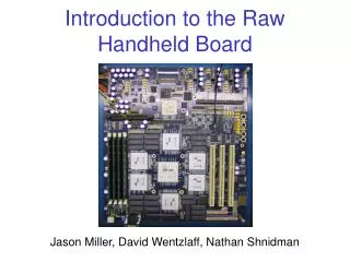
Introduction to the Raw Handheld Board Jason Miller, David Wentzlaff, Nathan Shnidman
Presentation Outline • Raw’s I/O ports (basic) • Memory sub-system • PCI and host PC connection • Expansion interface • Integrated peripherals and connectors • Raw’s I/O ports (detailed)
01_02 00 01 02 03 Tile Tile Tile Tile 15 04 Tile Tile Tile Tile 14 05 Tile Tile Tile Tile 13 06 Tile Tile Tile Tile 12 07 11 10 09 08 09_10 Raw Chip I/O Ports • I/O Multiplexing: • Drop ST2 • Round-robin arbitration for MDN, GDN and ST1 • Ports 01 & 02 and ports 09 & 10 are merged • 14 ports total • May be numbered in hex • Each port is actually separate input and output busses
Let’s start building a Raw board • Single Raw processor • 14 I/O ports Raw
Add a memory sub-system • 2 Xilinx XC2V3000 FPGAs for memory controllers • Separate memory controller on each port • 512 MB PC133 SDRAM DIMM for each controller • 128 MB address space for each tile by default MC0 512 MB DIMM Raw 512 MB DIMM MC1 512 MB DIMM 512 MB DIMM
Add a PCI sub-system • Xilinx XC2V3000 FPGA for PCI controller • Three 64-bit / 66 MHz PCI slots 64-bit PCI slot 64-bit PCI slot 64-bit PCI slot PCI MC0 512 MB DIMM Raw 512 MB DIMM MC1 512 MB DIMM 512 MB DIMM
Host PC with SLAAC-1V CONF Add a PCI sub-system • Xilinx XC2V3000 FPGA for PCI controller • Three 64-bit / 66 MHz PCI slots 64-bit PCI slot 64-bit PCI slot 64-bit PCI slot PCI MC0 512 MB DIMM Raw 512 MB DIMM MC1 512 MB DIMM 512 MB DIMM • Xilinx XC2V1000 FPGA for Config • “Backdoor interface” for connection to host PC
Host PC with SLAAC-1V CONF Add an expansion interface 190 pin MICTOR LE 64-bit PCI slot 64-bit PCI slot 64-bit PCI slot PCI MC0 512 MB DIMM Raw 512 MB DIMM MC1 512 MB DIMM 512 MB DIMM RE 190 pin MICTOR • Xilinx XC2V3000 FPGAs for LE and RE • 190-pin MICTOR connectors for general use
Host PC with SLAAC-1V CONF Finally, some I/O interfaces 190 pin MICTOR LE 64-bit PCI slot 64-bit PCI slot 64-bit PCI slot PCI MC0 512 MB DIMM Raw 512 MB DIMM PI MC1 512 MB DIMM Audio In/Out 512 MB DIMM 100 MHz ADC RE RS-232 Port Daughter-card Connector 190 pin MICTOR Keyboard Port LCD Connector • Xilinx XC2V3000 FPGA for controllers • Various integrated devices and connectors
Integrated I/O and Connectors • Audio frequency ADCs and DACs • 2 channels, up to 44.1 kHz, 16-bit samples, RCA jacks • High-speed analog to digital converter • Up to 100 MHz, 12 bit precision, SMB connector • Serial (RS-232) port w/ 16550 UART • 9-pin D-SUB connector • PS/2 keyboard port (controller in FPGA) • LCD connector • 4x40 character, text-only LCD display: Optrex DMC-40457 • Daughter-card connector • Planned: 100 Mbit Ethernet and USB 2.0 controllers • 50 signal pins, 66 MHz clock, 5V and 3.3V power
Raw Fabric System FPGA 512 MB DIMM Raw Raw 512 MB DIMM FPGA 512 MB DIMM 512 MB DIMM FPGA 64-bit PCI slot 64-bit PCI slot 64-bit PCI slot Raw Raw 190 pin MICTOR FPGA 2x2 Raw Board Peripheral Board
Raw I/O Ports (detailed) Sending Tile Receiving Tile Network Switch Data Network Switch Valid SIB Thanx
Raw I/O Ports (detailed) Sending Tile Receiving Tile A Network Switch Data Network Switch 1 A Valid SIB Thanx
Raw I/O Ports (detailed) Sending Tile Receiving Tile B Network Switch Data Network Switch 1 B A Valid SIB Thanx
Raw I/O Ports (detailed) Sending Tile Receiving Tile Network Switch Data Network Switch A B Valid 1 SIB Thanx
Normal Port: 2 Ready bits 3 Yummy bits Ready Encodings Double Port: 3 Ready bits 6 Yummy bits Ready Encodings 32 Data Out 2 Ready Out Yummy S In Yummy M In Yummy G In 00 = None 000 = None Raw 01 = Static 001 = Static Port 1 32 10 = Memory 010 = Memory Port 1 Data In 11 = General 011 = General Port 1 2 Ready In 100 = None Yummy S Out 101 = Static Port 2 Yummy M Out 110 = Memory Port 2 Yummy G Out 111 = General Port 2 Raw I/O Ports (detailed) Sending Tile Receiving Tile Network Switch Data Network Switch Valid SIB Thanx